Review
. 2021 Nov 24;121(22):13701-13796.
doi: 10.1021/acs.chemrev.1c00308. Epub 2021 Aug 18.

Protein Assembly by Design

Affiliations
Review

Protein Assembly by Design

Jie Zhu et al. Chem Rev. .

Abstract

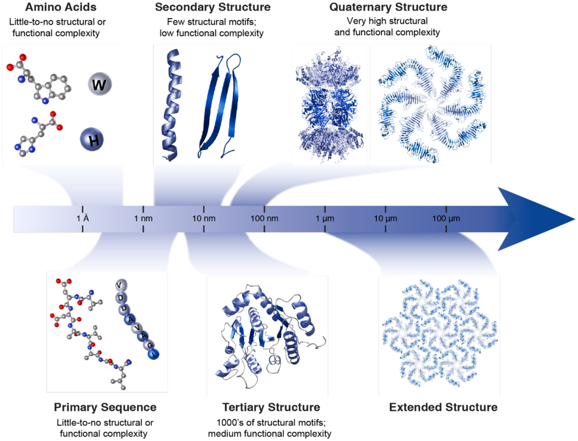
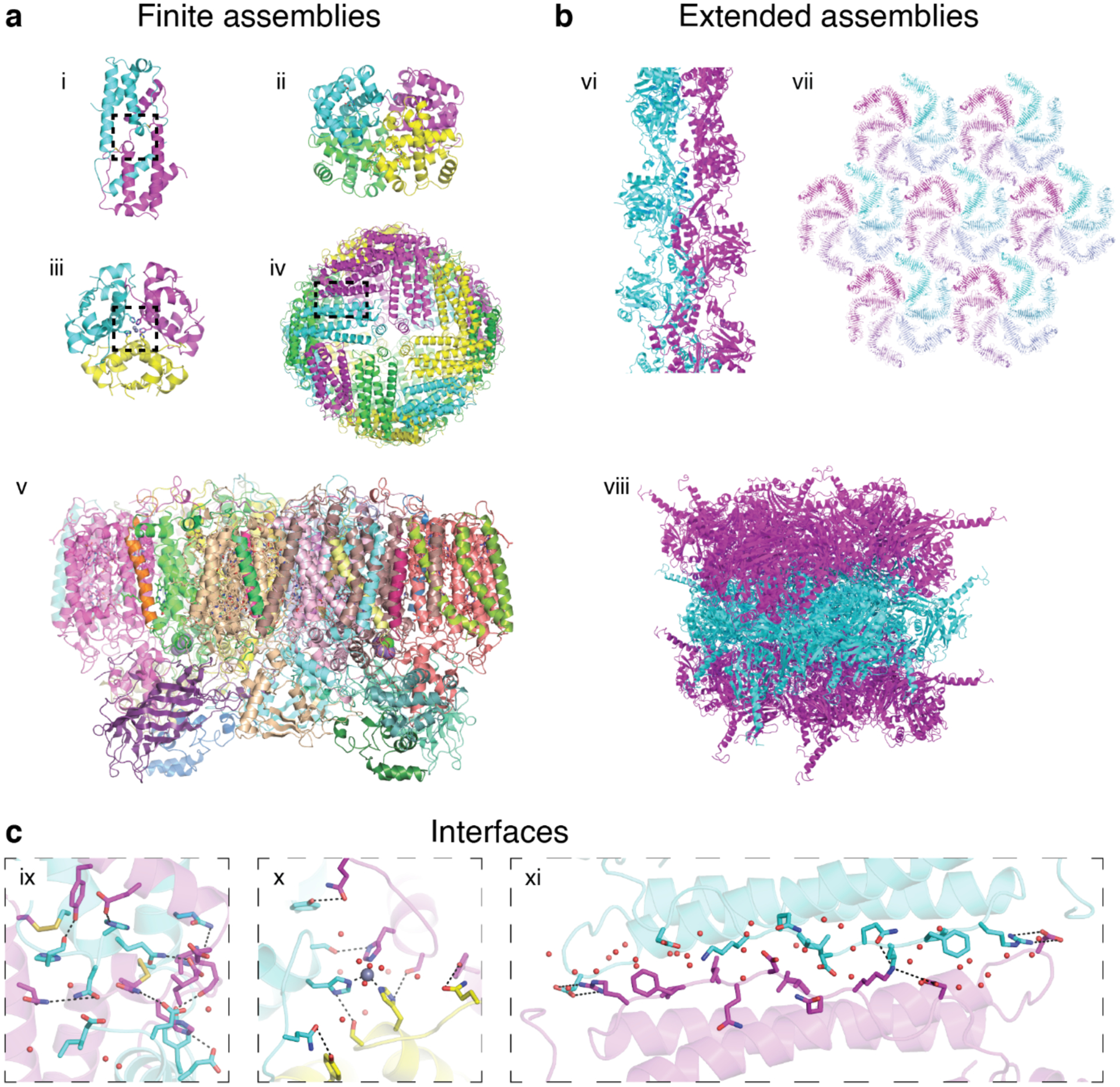
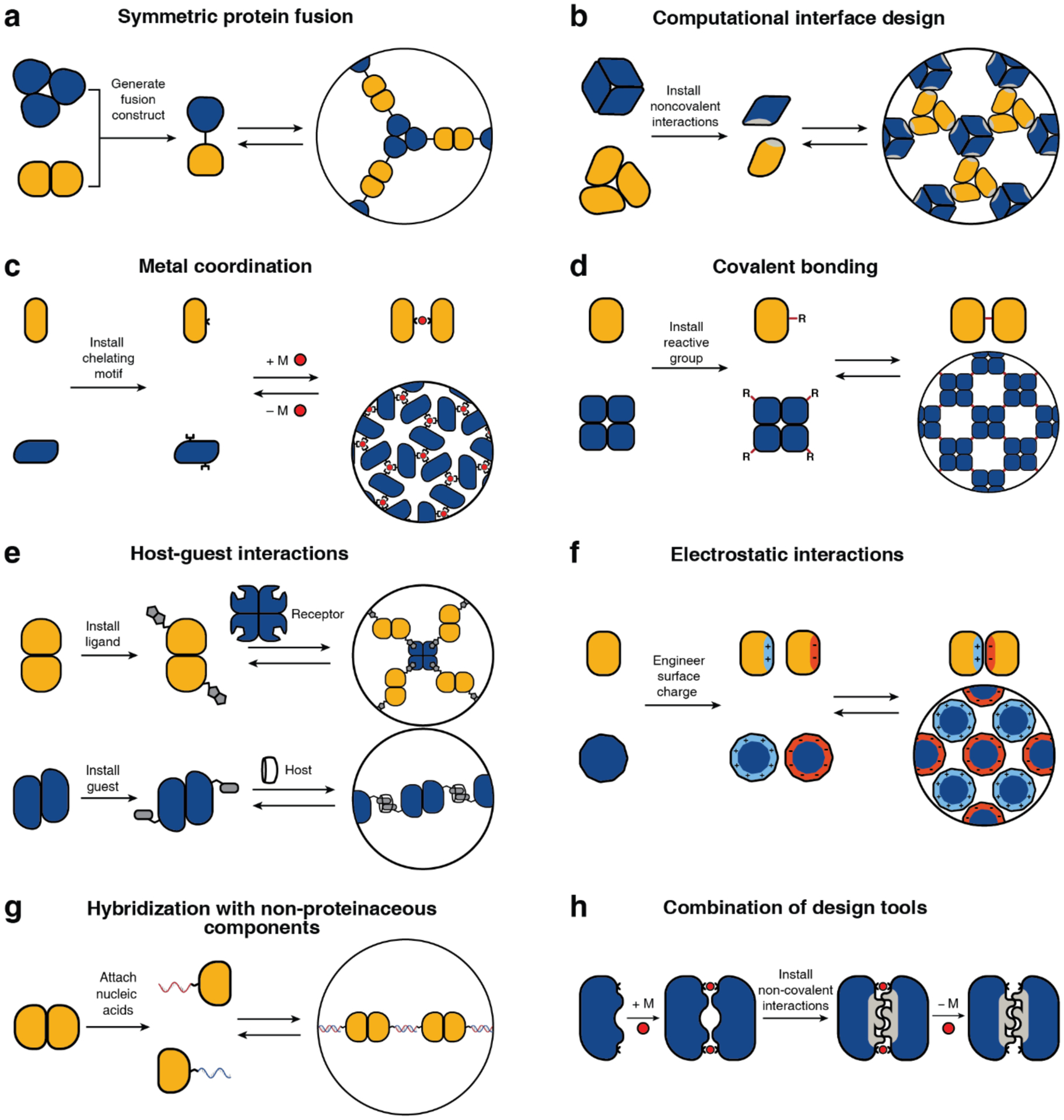
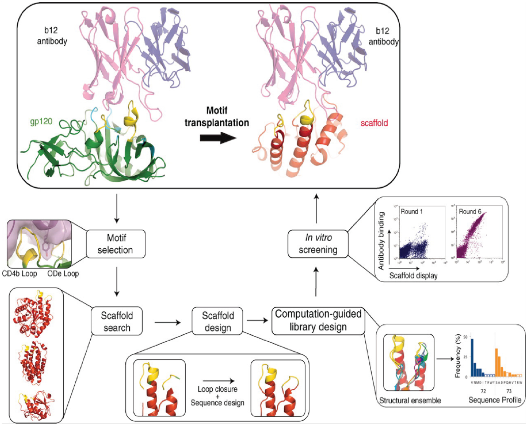
Proteins are nature's primary building blocks for the construction of sophisticated molecular machines and dynamic materials, ranging from protein complexes such as photosystem II and nitrogenase that drive biogeochemical cycles to cytoskeletal assemblies and muscle fibers for motion. Such natural systems have inspired extensive efforts in the rational design of artificial protein assemblies in the last two decades. As molecular building blocks, proteins are highly complex, in terms of both their three-dimensional structures and chemical compositions. To enable control over the self-assembly of such complex molecules, scientists have devised many creative strategies by combining tools and principles of experimental and computational biophysics, supramolecular chemistry, inorganic chemistry, materials science, and polymer chemistry, among others. Owing to these innovative strategies, what started as a purely structure-building exercise two decades ago has, in short order, led to artificial protein assemblies with unprecedented structures and functions and protein-based materials with unusual properties. Our goal in this review is to give an overview of this exciting and highly interdisciplinary area of research, first outlining the design strategies and tools that have been devised for controlling protein self-assembly, then describing the diverse structures of artificial protein assemblies, and finally highlighting the emergent properties and functions of these assemblies.


Figures

Figure 1.
Figure 1.
Complexification of protein assembly, from ångström-scale amino acids to extended, micron-scale protein structures. Individual amino acids are first covalently linked to form unstructured polymers, termed polypeptides. Polypeptides adopt secondary structure motifs, such as α-helices and β-strands, that combine to determine the tertiary structures of proteins. Discrete, folded polypeptides with either identical or distinct tertiary structures can assemble via non-covalent interactions into supramolecular complexes, termed quaternary structures. Further non-covalent interactions at the interfaces of symmetric quaternary structures can give rise to extended structures, exemplified here by a bacterial S-layer structure.
Figure 2.
Figure 2.
Protein evolution entails the incorporation of a small structural module into a larger, functional tertiary fold, which can then associate with other functional domains to form quaternary assemblies with diverse, multi-component functions. This process is exemplified here with the βαβ motif-containing Rossmann fold, which is part of protein complexes with functions spanning histone deacetylation (sirtuin), DNA repair (photolyase), and dinitrogen reduction (nitrogenase). In all three quaternary assemblies, the Rossmann fold functions as the nucleotide-binding domain.
Figure 3.
Figure 3.
Finite and extended natural protein assemblies. a) Examples of finite protein assemblies: Interleukin-5 (i, PDB ID: 1HUL), hemoglobin (ii, PDB ID: 1HHO), insulin (iii, PDB ID: 1ZNI), human heavy chain ferritin (iv, PDB ID: 6B8F), and photosystem II (v, PDB ID: 1AXT). b) Examples of extended protein assemblies: 1D actin filament (vi, PDB ID: 6BNO), 2D S-layer (vii, PDB ID: 5N8P) and 3D infectious cytoplasmic polyhedrosis virus protein crystal (viii, PDB ID: 2OH5). c) Close-up views of protein-protein interfaces of interleukin-5 (ix), insulin (x), and ferritin (xi) highlighting non-covalent, covalent, and metal-mediated interactions. In addition to these enthalpic contributions, the expulsion of waters upon the burial of interfacial amino acid residues (i.e., the “hydrophobic effect”) represents an important entropic contribution to interface stability.
Figure 4.
Figure 4.
Schematic representation of the design tools and strategies for protein self-assembly, which encompass non-covalent, covalent, and metal-mediated interactions. Each strategy has been successfully used to construct both finite and extended assemblies with a wide array of protein building blocks. Selection of the design strategy is largely dictated by the desired stability, selectivity, and reversibility of the target assembly.
Figure 5.
Figure 5.
Conformational changes in domain-swapped hCRBPII. a) Structure of the W60 hCRBPII domain-swapped dimer. b) Overlay of the hCRBPII monomer (red) and the W60 hCRBPII domain-swapped dimer (cyan). c) Comparison of the apo (green) and holo (magenta) states of the D51 hCRBPII domain-swapped dimer. Binding of retinal results in significant conformational changes. (a) Adapted with permission from Ref. 319. Copyright 2016 Elsevier. (b) Adapted with permission from Ref. 319. Copyright 2016 Elsevier. (c) Adapted with permission from Ref. 320. Copyright 2019 ACS.
Figure 6.
Figure 6.
Domain swapping by mutually exclusive folding. a) Insertion of Ub into a loop in RBP. b) Schematic of domain swapping by mutually exclusive folding. c) Activation of protein function by domain swapping. Adapted with permission from Ref.. Copyright 2015 Elsevier.
Figure 7.
Figure 7.
Domain swapping by insertion of a QVVAG motif. a) Cartoon depiction of domain swapping via the QVVAG hinge loop. b) Structure of the MNEI single domain-swapped dimer. c) Structure of the MNEI double domain-swapped dimer. Adapted with permission from Ref.. Copyright 2019 NPG.
Figure 8.
Figure 8.
Computational and experimental steps for the transplantation of a structural motif to a new scaffold. Scaffolds can either be chosen by searching the PDB for existing structures or by designing a desired fold around the motif using ab initio folding calculations. Adapted with permission from Ref.. Copyright 2011 AAAS.
Figure 9.
Figure 9.
Computational docking calculations can be used to sample possible binding modes, from which the resulting protein-protein interface can be designed to obtain dimeric complexes. Adapted with permission from Ref.. Copyright 2019 NPG.
Figure 10.
Figure 10.
Overview of protein-protein interface design via “hot-spot” residues as applied to the design of proteins that bind to influenza hemagglutinin. Adapted with permission from Ref.. Copyright 2011 AAAS.
Figure 11.
Figure 11.
Metal-mediated dimerization of cyt cb562 via a) Cu2+ binding to a pair of i/i+4 bis-His motifs or b) Ni2+ binding to a His residue and a hydroxyquinoline chelate in an i/i+7 arrangement. (a) Adapted with permission from Ref.. Copyright 2009 ACS. (b) Adapted with permission from Ref.. Copyright 2010 ACS.
Figure 12.
Figure 12.
Design model and structure of MID1. a) Computational design model of MID1. b) Comparison of the MID1 design model (tan) and crystal structure (cyan). Adapted with permission from Ref.. Copyright 2012 ACS.
Figure 13.
Figure 13.
Metal Active Sites by Covalent Tethering (MASCoT). a) Implementation of MASCoT. The C96-C96 disulfide bond covalently tethers two proteins, forming a nascent protein-protein interface that is locked into place upon metal addition. b-e) Formation of metal binding sites with different primary and secondary coordination spheres. Adapted with permission from Ref.. Copyright 2019 NPG.
Figure 14.
Figure 14.
Design of symmetric homo-oligomers from proteins with repeating units. a) Design of a two-fold symmetric (βα)8-barrel. The two halves are soluble as monomeric proteins that assemble into a dimeric barrel. b) Crystal structures of Pizza6 proteins with different oligomeric states. From left to right: wild-type protein used as a template for Pizza6 design, Pizza2 (trimer), Pizza3 (dimer), Pizza6 (monomer). (a) Adapted with permission from Ref.. Copyright 2011 ACS. (b) Adapted with permission from Ref.. Copyright 2014 National Academy of Sciences.
Figure 15.
Figure 15.
Computational design of α-helical toroids. The protocol consists of a) ab initio folding to generate backbone conformations, b) sequence design of conformations, c) filtering to remove poor designs, d) clustering of results to identify recurring packing arrangements, e) resampling of structures from the clusters, and f) a final assessment of results by re-predicting the designed structures from their sequences. Adapted with permission from Ref.. Copyright 2015 NPG.
Figure 16.
Figure 16.
Computational design of cyclic homo-oligomers. a) Monomers are first docked in cyclic geometries using low-resolution, symmetric docking. b) Docked oligomers are then scored using a residue-pair transform (RPX) method which models side-chain interactions implicitly. c) The best scoring geometries are finally subjected to interface design. Adapted with permission from Ref.. Copyright 2016 NPG.
Figure 17.
Figure 17.
Design of coiled-coil oligomers via HBNet. a) HBNet precomputes the hydrogen bond and repulsive interaction energies between side chains for all possible rotamers at a set of selected positions. This information is stored in a graph structure; traversing the graph reveals the combinations of hydrogen-bonding rotamers that form a hydrogen bond network. b) Design of homo-oligomers by sequentially designing coiled-coil backbones, using HBNet to identify hydrogen bonding networks that connect two-helix monomers, and designing the remaining residues around the hydrogen bonding network to accommodate the network. Adapted with permission from Ref.. Copyright 2016 AAAS.
Figure 18.
Figure 18.
Crystal structures of de novo designed transmembrane oligomers. a) Model of the dimeric transmembrane protein, indicating the position of the amphipathic (YW) and positively charged (RK) rings. b) Comparison between the crystal structure and design model of a transmembrane dimer. c) Crystal structure and design model of the transmembrane tetramer. Adapted with permission from Ref.. Copyright 2018 AAAS.
Figure 19.
Figure 19.
Computationally designed, oligomeric transmembrane pores. a) Overlay between the crystal structure (blue) and design model (grey) of the water-soluble hexamer. b) Overlay between the crystal structure (blue) and design model (grey) of the water-soluble octamer. A slight tilt in the monomers results in a greater deviation from the design model than in the hexameric case. c) Cryo-EM structure of the tetrameric transmembrane pore. Adapted with permission from Ref.. Copyright 2020 NPG.
Figure 20.
Figure 20.
Oligomerization of oppositely supercharged Cerulean (Ceru) and GFP variants mediated by electrostatic interactions. a) Hypothesized model of symmetric oligomers and long-range assembly of oppositely supercharged monomeric proteins. b) Supercharged GFP variants engineered by mutating the surface residues of sfGFP to basic (blue) or acidic (yellow) residues. c) Cryo-EM reconstruction of the Ceru+32/GFP−17 16-mer at 3.47 Å resolution in three different orientations. Adapted with permission from Ref.. Copyright 2019 NPG.
Figure 21.
Figure 21.
Genetic fusion strategy for self-assembly of WA20-Foldon fusion protein using native trimerization of Foldon. Adapted with permission from Ref.. Copyright 2015 ACS.
Figure 22.
Figure 22.
Discrete formation of GFP polygons by GFP1–10 with N-terminal-fused GFP11. The intermolecular incorporation of β-strand 11 into the β-barrel of GFP 1–10 guides stable oligomerizations from dimeric to decameric structures. Adapted with permission from Ref.. Copyright 2015 NPG.
Figure 23.
Figure 23.
MDPSA and MeTIR strategies for metal-mediated oligomerization. In MDPSA, metal-chelating motifs are installed on the surface of target proteins, thereby guiding protein self-assembly through metal-coordination. In MeTIR strategy, metal-directed protein assemblies are redesigned using non-covalent interactions and a covalent linker at the protein-protein interface. The sequential design approach through MDPSA and MeTIR results in the formation of stable oligomers without the aid of metal ions. Adapted with permission from Ref. 83. Copyright 2016 Elsevier.
Figure 24.
Figure 24.
Metal-mediated protein oligomers based on cyt cb562 as a building block. a) Design of cyt cb562 oligomers using the MDPSA approach. In the MBPC2 variant, surface-exposed bis-His clamps are located at residues 59/63 and 73/77. Depending on the metal ion coordination preferences, different oligomerization states are achieved – Ni2:MBPC13 trimer (top), Cu2:MBPC12 dimer (middle), and Zn4:MBPC14 tetramer (bottom). b) In the MBPC2 variants, the R62D and D74A mutations give rise to the Zn4:MBPC24 tetramer where the orientation of the protein monomers is inverted. c) MeTIR strategy for redesigning the interface of Zn4:MBPC14. i1 interface of Zn4:MBPC14 tetramer is redesigned to install hydrophobic residues and create the stabilized Zn4:RIDC14 tetramer. (b) Adapted with permission from Ref.. Copyright 2008 ACS. (c) Adapted with permission from Ref.. Copyright 2019 ACS.
Figure 25.
Figure 25.
Overview of a designed supramolecular protein assembly with catalytic metal sites. a) Tetrameric structure of Zn2+-bound C96RIDC14. b) List of C96RIDC14 variants with potential catalytic Zn2+-binding sites on the outer surface of the tetramer. c) Crystal structure of AB3 which forms the stable tetramer with catalytic Zn2+ binding sites. Adapted with permission from Ref.. Copyright 2014 AAAS.
Figure 26.
Figure 26.
TriCyt series of metal-mediated protein trimers. a) Crystal structure of Ni2+:(TriCyt1)3. b) Sedimentation coefficient distributions of apo-TriCyt2 (black) and Mn2+:(TriCyt2)3. c) Crystal structure of Fe2+:(TriCyt2)3 superimposed to Ni2+:(TriCyt1)3. d) Hydrophobic packing and electrostatic interaction newly added to the trimer interface of Fe2+:(TriCyt2)3. e) Sedimentation coefficient distributions of apo-TriCyt3 (black) and Mn2+:(TriCyt3)3. f) Crystal structure of Co2+:(TriCyt3)3 and hydrogen-bonding networks in the trimer interface. g) Hexa-his coordination environment of Mn2+ in Mn2+:(TriCyt3)3. Adapted with permission from Ref.. Copyright 2020 Wiley.
Figure 27.
Figure 27.
Design of protein cages by genetic fusion using α-helical peptides as linkers. a) Illustration of the geometric design principle of genetic fusion. Crystal structure of designed 12-mer tetrahedral cage (b) and 24-mer cubic cage (c). Natural oligomers used as building blocks (left) and genetically fused components, assembled into symmetric cage structures (right). (a) Adapted with permission from Ref.. Copyright 2012 AAAS. (b) Adapted with permission from Ref.. Copyright 2012 AAAS. (c) Adapted with permission from Ref.. Copyright 2014 NPG.
Figure 28.
Figure 28.
Design of protein icosahedral cage by a double-fusion protein with three symmetry components. Adapted from Ref.. Copyright 2020 ACS.
Figure 29.
Figure 29.
Design scheme of protein cages by genetic fusion using oligomers and coiled-coil domains. a) Trimeric KDGP-aldolase building blocks connected with antiparallel coiled-coil domains self-assemble into heterogeneous structures. b) Different combinations of symmetry elements are obtained by fusing the C-terminus of a trimeric protein to coiled-coil-forming peptides with different oligomerization states. Protein cages of different geometry are observed by ns-TEM or cryo-EM. (a-b) Adapted with permission from Ref.. Copyright 2017 Wiley. (b) Adapted with permission from Ref.. Copyright 2016 National Academy of Science. Adapted with permission from Ref.. Copyright 2019 ACS.
Figure 30.
Figure 30.
Overview of two-component tetrahedral protein cages developed by computational design. a) Symmetric docking of two distinct trimeric proteins to design a tetrahedral cage (T33). Atomic structure (b) and ns-TEM images (c) of T33–15. Two-fold and three-fold views are shown. d) Redesign of protein-protein interfaces between two trimers. e) The T32 cage is constructed with one trimeric and one dimeric building blocks. Crystal structure (f) and ns-TEM results (h) are shown. Insets in (c) and (h) show projections calculated from the computationally designed model (left) and class averages of the particles from microscopy (right). Adapted with permission from Ref.. Copyright 2014 NPG.
Figure 31.
Figure 31.
Overview of two-component icosahedral protein cages constructed through a computational design method. Icosahedral cages created by combining building blocks with different rotational symmetry were designed: I53–40 (a-c), I52–32 (d-f) and I32–28 (g-i). (a, d, g) show icosahedra outlined in gray dashed lines with three different combinations of symmetry axes (left). Models created by aligning pentameric, trimeric and dimeric proteins along target symmetry axes. Translational and rotational parameters are optimized by systematic screening. (b, e, h) Crystal structures of the designed cages. Views are shown along three-fold, two-fold and five-fold axes. (c, f, i) ns-TEM characterization of the designed cages (100 nm scale bar). Adapted with permission from Ref.. Copyright 2016 AAAS.
Figure 32.
Figure 32.
Design of an icosahedral cage based on single component. a-c) Symmetric docking of trimeric building block to an icosahedral structure. d) Sequence design yields low-energy interfaces after mutation on five residues. Adapted with permission from Ref.. Copyright 2016 NPG.
Figure 33.
Figure 33.
Model designs and structural characterizations of AbCs by cryo-EM. a) D2 Dihedral d2.7; b) T32 tetrahedral t32.4; c) O42 octahedral o42.1; d) I52 icosahedral i52.3. Combination of building blocks into a target cage geometry (left) and cryo-EM reconstructions (right). Adapted with permission from Ref.. Copyright 2021 AAAS.
Figure 34.
Figure 34.
Zn2+-mediated tetrahedral protein cage in ordered lattice. Adapted with permission from Ref.. Copyright 2020 NPG.
Figure 35.
Figure 35.
Metal-mediated TRAP-cage assembly. a) Cys-substituted 11-mer TRAP ring. b) Au-TPPMS structure. c) Left-handed TRAP-cage model and electron density map. The arrowheads indicate density bridges connecting neighboring TRAP rings. d) ns-TEM images of cages purified by SEC after incubating TRAP with Au-TPPMS for 3 days. Overall fits of the final TRAP-cage models onto their respective density maps: left-handed (e) and right-handed (f) structures. Adapted with permission from Ref.. Copyright 2019 NPG.
Figure 36.
Figure 36.
Metal-mediated protein cage via orthogonal chemical interactions. a) Structural overview of the cyt cb562 scaffold. Salient structural elements are shown as sticks. b) C2-symmetric protein dimerization induced by tetrahedral Zn2+ coordination of native amino acid side chains. c) C3-symmetric protein trimerization induced by octahedral Fe3+-tris-hydroxamate coordination. Surface representations of the BMC3 cage (d) and BMC4 cage (e), with metal ions shown as colored spheres. Insets show atomic details of each metal coordination site, with the mFoDFc electron density omit map (blue mesh) contoured at 3σ. Adapted with permission from Ref.. Copyright 2020 NPG.
Figure 37.
Figure 37.
Copper-inducible ferritin cage assembly. a) Schematic illustration of the reverse metal-templated interface redesign (rMeTIR) process. b) Ferritin cage viewed down the C2 symmetry axis. c) The crystal structure of Cu2+-bound MIC1 cage. d) Close-up view of the C2 interface of the Cu2+-bound MIC1 cage. e) Close-up view of the C2 interface of the MIC1 cage (apo-MIC1) obtained after the chelation of copper ions with EDTA. f) Sedimentation velocity profile of MIC1 in the different states: as-isolated, monomeric; Cu2+-induced cage; EDTA-treated cage; Cu2+-reconstituted cage. g) ns-TEM images of MIC1 in different states: monomeric, Cu2+-induced cage, and apo-cage. Scale bars, 50 nm. Adapted with permission from Ref.. Copyright 2013 NPG.
Figure 38.
Figure 38.
Ferritin cage reengineering into structures with different sizes and geometries. a) Conversion of the 24-mer ferritin cage into 8-mer nanorings with D4 symmetry and a 3D porous protein lattice. b) Conversion of the 8-mer bowl-like nanoring into higher-order structures via disulfide bond formation. (a) Adapted with permission from Ref.. Copyright 2018 ACS. (b) Adapted with permission from Ref.. Copyright 2019 NPG.
Figure 39.
Figure 39.
Circular permutation of Aquifex aeolicus lumazine synthase (AaLS). a) Design of circularly permuted AaLS (cpAaLS). b) ns-TEM images of cpAaLS with linkers of varying length, cpAaLS(LxHy), where x and y represent the number of total amino acids and His residues, respectively (100 nm scale bar). Adapted from Ref.. Copyright 2018 RSC.
Figure 40.
Figure 40.
Fibrillar protein self-assembly through apo-hemoprotein/heme interactions. a) H63C and A125C mutations are incorporated into cytochrome b562 (Cyt) and myoglobin (Mb) respectively to position Cys residues on the protein surface for further conjugation to artificial heme derivatives. Under low pH conditions, the native heme cofactor is removed from the heme pocket. After reconstitution at physiological pH conditions, hemoprotein assemblies are obtained via artificial heme-heme pocket interactions. b) Heterotypic co-assembly of dimerized apomyoglobin (apo-MbA125C)2 and streptavidin (Sav) is achieved using a bis(biotin)-heme bifunctional ligand. Adapted with permission from Ref.. Copyright 2012 RSC.
Figure 41.
Figure 41.
Formation of GST homodimer nanowires via host-guest interactions. The phenylalanine-glycine-glycine (FGG) motifs fused to the N-termini of GST serve as guest molecules binding to the cucurbit[8]uril (CB[8]) macrocyclic host. Adapted with permission from Ref.. Copyright 2013 Wiley.
Figure 42.
Figure 42.
Formation of helical microtubules based on dual interactions. a) Soybean agglutinin (SBA) tetramers (left) associate with dual-function ligands to form microtubules via protein-sugar binding and π-π stacking. The ligand (middle) is composed of a protein-binding sugar moiety, a variable-length linker and a dimerizing RhB moiety. Microtubule cryo-EM micrograph (right), scale bar: 25 nm. b) Model of microtubule based on cryo-EM reconstruction. Three helical filaments compose the microtubule, where each helical turn consists of nine tetramer units. Adapted with permission from Ref.. Copyright 2016 ACS.
Figure 43.
Figure 43.
Design of covalently linked Hcp1 nanotube based on crystal packing. a) Structure of the Hcp1 hexameric ring viewed from top, bottom, and in cross-section exposing the interior surface of the pore. b) The honeycomb lattice packing of Hcp1 crystal viewed from the z-axis, showing stacking of Hcp1 rings into nanotubes. c) Side view of the nanotube formed by five G90C/R157CHcp1 rings (grey) and two capping units (green and blue) modified with Cys residues only on one side. Adapted with permission from Ref.. Copyright 2008 National Academy of Sciences.
Figure 44.
Figure 44.
Covalently linked protein filaments based on the TbCatB protein. a) Illustration of the process to generate covalently linked R91C/T223CTbCatB protein filament bundles. Overexpression of TbCatB gives rise to protein crystals in vivo. During isolation, the crystals undergo autoxidation which links monomers by disulfide bonding into filaments that can be recovered by dissolving the crystals. b) Design of R91C/T223CTbCatB filament based on the P42212 crystal structure. c) Zig-zag protein arrangement in the two-filament bundle isolated upon crystal dissolution. Adapted with permission from Ref. Copyright 2021 Wiley.
Figure 45.
Figure 45.
Mg2+-mediated assembly of GroEL nanotubes. a) The apical domains of GroEL are labeled with spiropyran (SP) which undergoes spontaneous isomerization to merocyanine (MC) in solution. b) GroELMC nanotube formation induced by Mg2+. Adapted with permission from Ref.. Copyright 2013 ACS.
Figure 46.
Figure 46.
Zn2+-mediated assembly of RIDC3, a metal-binding cyt cb562 variant. a) The RIDC3 monomer undergoes dimerization upon Zn2+ coordination at the high affinity site. Amino acids that stabilize the interface in the C2-symmetric dimer are shown in cyan, the high- and low-affinity Zn binding sites are depicted in magenta and pink, respectively. b) Zn-mediated RIDC3 self-assembly into different morphologies under fast and slow nucleation conditions. High pH or high [Zn]:[RIDC3] ratio enables fast nucleation, giving rise to more nuclei which form the helical nanotubes. Low pH and low [Zn]:[RIDC3] give rise to fewer nuclei that grow into 2D and 3D crystals. c) Zn-mediated packing of RIDC3 monomers in the 2D crystal plane based on XRD (left). Close-up views of the three different Zn2+ binding environments found in the 2D RIDC3 crystals (right). d) RIDC3 nanotube reconstruction from cryo-EM micrographs (left). Zoomed-in representation of the packing of RIDC3 molecules highlighting interaction planes where different Zn2+ coordination environments are found (right). Cryo-EM micrograph of an RIDC3 nanotube (bottom). e) Structure of the tetrameric H59/C96RIDC3 building block formed via disulfide bonding and Zn coordination (left). Three classes of nanotubes with controllable diameters form under different solution conditions. (a-d) Adapted with permission from Ref.. Copyright 2012 NPG. (e) Adapted with permission from Ref.. Copyright 2015 ACS.
Figure 47.
Figure 47.
Assembly of SP1 nanowires via multivalent electrostatic interactions. a) Top and side views of the SP1 ring with structure with charge distribution on the surface. The color scale goes from negative (red) to positive (blue) charge. b) Illustration of a generation 5 PAMAM dendrimer (PD5) (left) and co-assembly of PD5 and SP1 into nanowires (right). c) Illustration of SP1 nanowire formation mediated by multivalent interactions with ethylenediamine. (a-b) Adapted with permission from Ref. 52. Copyright 2015 ACS. (c) Adapted with permission from Ref.. Copyright 2016 RSC.
Figure 48.
Figure 48.
Protein-DNA nanowires. a) Illustration of the co-assembly of computationally designed ENH dimers and dsDNA into a linear nanowire. b) Co-crystal structure shows that kinked wires are formed. c) AFM image of the protein-DNA nanowire. Adapted with permission from Ref.. Copyright 2015 NPG.
Figure 49.
Figure 49.
Computationally designed helical protein filaments. a) Computational protocol to design self-assembling protein filaments. A copy of an asymmetric protein monomer is randomly rotated and moved, then slid into contact with the first monomer. The operation is repeated to generate helices. Cyclic symmetry and the ordering of contacting units are screened, and sequence of the monomer is redesigned to optimize the interfaces. b) From left to right: Computationally designed models, cryo-EM micrographs, cryo-EM structures, and overlay of designed model and cryo-EM structure for the C3 symmetric DHF91 (top) and the C1 symmetric DHF79 (bottom) designs. c) Fibers with variable diameter can be generated by changing the number of repeat units within the monomer. Computationally designed models (top) and 2D class average structures (bottom) are shown for two variants of the DHF58 filament. Adapted with permission from Ref.. Copyright 2018 AAAS.
Figure 50.
Figure 50.
Genetic fusion approach to 2D protein assembly. Self-assembly of binary 2D arrays along the C2 symmetry axis shared by the components. The homologous D4-symmetric protein building block ALAD is combined with a) a heterologous D2-symmetric assembly motif (Streptavidin/Streptag I) or b) a heterologous C2-symmetric assembly motif (Lac21E/Lac21K). Adapted with permission from Ref.. Copyright 2011 NPG.
Figure 51.
Figure 51.
Assembly of 2D crystals based on C4-symmetric RhuA modified at the corners to enable C2 connectivity between building blocks. a) C98RhuA forms a p4212 lattice following oxidation. b) H63/H98RhuA forms a p4 lattice following divalent metal coordination. TEM characterization of 2D crystals of RhuA variants: (I) Low-magnification views of RhuA crystals, (II) high-magnification views of RhuA crystals with the Fast Fourier transforms (inset), (III) reconstructed 2D images, and (IV) structural models based on (III). Adapted with permission from Ref.. Copyright 2016 NPG.
Figure 52.
Figure 52.
Covalently linked protein nanosheets based on the S98Y variant of cricoid stable protein 1 (SP1). a) Tyrosine crosslinking at the periphery of the SP1 disk can be carried either via a single enzyme pathway with horseradish peroxidase (HRP) and H2O2, or a dual enzyme pathway with HRP, glucose oxidase (GOx) and glucose. b) TEM characterization of the protein nanosheets with inset showing an enlarged area of the micrograph and a model of hexagonal packing of the SP1 disks. Adapted with permission from Ref.. Copyright 2017 ACS.
Figure 53.
Figure 53.
Covalently linked 2D HuHF arrays. a) A single mutation near the C4 axis positions four Cys residues in close proximity to each other. Slow oxidation yields ordered 2D HuHF arrays through multivalent disulfide bond formation at the “hot spots”. b) ns-TEM characterization of the square lattice. Adapted with permission from Ref.. Copyright 2019 RSC.
Figure 54.
Figure 54.
Covalently crosslinked TMVCP nanosheets. a) A schematic diagram of the formation of TMVCP 2D nanosheets upon oxidation of the peripheral Cys residues by Cu2+. Characterization of the nanosheets by b) ns-TEM, c) AFM, and d) high resolution ns-TEM. Inset shows the corresponding FFT. Adapted with permission from Ref.. Copyright 2018 ACS.
Figure 55.
Figure 55.
Artificial metal-dependent nucleoprotein assemblies based on a chimeric RIDC3-DNA building block. a) RIDC3-DNA hybrids (left). TEM characterization (middle) and reconstructed 2D cryo-EM map (right) of the RIDC3-DNA 2D crystals. MD-minimized models and cartoon illustrations of b) a single 2D RIDC3–DNA layer and c) the 3D stacking of two RIDC3–DNA layers. Adapted with permission from Ref.. Copyright 2018 ACS.
Figure 56.
Figure 56.
Assembly of biotin-labeled RhuA with streptavidin. a) Schematic representation of the C4-symmetric enzyme RhuA with point mutation for biotin labeling (bR). Streptavidin (S) binds to two biotin labels on each side of bR, to form the building block bR•S. bbS, S bound to bis-biotin linkers, is further bound to bR•S. b) Association of bR and S building blocks imaged by ns-TEM. Clockwise from top left: bR•S4, bR2•S7, bR4•S16bbS12, and bR4•S12. c) Self-assembled networks produced from bR with bR•S4 (left) and bR•S4 with (bbS•S)x (right) imaged by ns-TEM. Adapted with permission from Ref.. Copyright 2003 AAAS.
Figure 57.
Figure 57.
Assembly of LecA via a combination of ligand binding and RhB dimerization. a) Structure of the tetrameric protein, LecA and inducing ligand RnG (n = 1 to 5). Cartoon representation of LecA/RnG dimerization. b) The three packing patterns of LecA/RnG based on the dimerization of RnG. c) Schematic representation of diagonal-diagonal packing of LecA/R2G (left) and enlarged cryo-EM images of a LecA/R5G 2D lattice. Adapted with permission from Ref.. Copyright 2017 Wiley.
Figure 58.
Figure 58.
Pascal triangle lattice formation from wheat germ agglutinin (WGA) and sialyllactoside-RhB (R-SL). a) Structure of the WGA dimer. b) Structure of assembly-inducing ligand (R-SL). c) Proposed mechanism of WGA assembly with R-SL. d) Cryo-EM characterization of the WGA 2D lattices. Inset: enlarged image. e) Cryo-EM images of the 2D lattice (left), and the overlay of the structural model (right). Adapted with permission from Ref.. Copyright 2020 Wiley.
Figure 59.
Figure 59.
Computationally designed 2D lattices with p321, p4212, and p6 layer group symmetry (designs p3Z_42, p4Z_i9, p6_9H). a) Packing of the designed lattices with the representation of the unit cells. b) Schematic representations of the designed 2D arrays. c) Designed interfaces between protein building blocks. d) ns-TEM characterization of the designed 2D lattices. Inset: enlarged image and FFT of the ns-TEM image. e) Projection map calculated from (d), and the overlay of the designed model on the projection map. Adapted with permission from Ref.. Copyright 2015 AAAS.
Figure 60.
Figure 60.
Computationally designed binary 2D protein arrays. a) Orientation of the D3 and D2 symmetric protein building blocks to form a heterogeneous p6m protein assembly (left). Top view of the p6m symmetry operators and the lattice spacing degree of freedom, d (middle). A plausible arrangement of D3 and D2 symmetric building blocks to form p6m lattices (right). b) Interface between the two protein building blocks. c) ns-TEM characterization of p6m arrays formed in E.coli upon co-expression of the two protein building blocks. Adapted with permission from Ref.. Copyright 2021 NPG.
Figure 61.
Figure 61.
Assembly of de novo designed helical repeat proteins at the muscovite mica interface. a) Schematic representation of DHR10-mica18 protein binding to the mica substrate through the modulation of a layer of K+ sublattice. b) The protein-mica interface design model predicted the orientation of DHR10-mica18 on K+-saturated mica surface. c) The three predominant orientations of DHR10-mica18 bound to the mica surface with the layer of K+ sublattice characterized by AFM. Assemblies of different variants of de novo designed helical proteins observed by AFM on mica treated with 3 M KCl: d) DHR10-mica18, e) DHR-mica6-NC and f) DHR-mica6-H. Adapted with permission from Ref.. Copyright 2019 NPG.
Figure 62.
Figure 62.
C98RhuA assembly at the mica interface. a) Schematic diagram of the negatively charged C-terminal face and partially positively charged N-terminal face of the C98RhuA tetramer (left), and the large dipole moment of the tetrameric protein (right). b) Preferential adsorption of either the N-terminal or the C-terminal face of RhuA depends on the charge state of the mica template. c) C98RhuA tetramer assembly pathways in solution and templated by the mica surface. Adapted with permission from Ref.. Copyright 2020 NPG.
Figure 63.
Figure 63.
HuHF crystallization facilitated by Ca2+ contacts at K86Q residues.
Figure 64.
Figure 64.
Assembly of charged HuHF lattices. Under low Mg2+ concentration conditions, the mixture of positively and negatively charged HuHF forms a tetragonal binary lattice, whereas when Mg2+ concentration is raised, cubic lattices composed only of the negatively charged variants and mediated by Mg2+ contacts are observed. Adapted with permission from Ref.. Copyright 2018 ACS.
Figure 65.
Figure 65.
Synthetic symmetrization via Cys residues introduced by mutagenesis. a) Illustration of synthetic symmetrization. An asymmetric protein monomer is represented by the figure “5.” Cys residues introduced at different positions on the surface are shown in yellow. Dimerization is achieved via disulfide bond formation. Trimerization requires a trivalent mediator. b) Illustration of the approach using CelA. Eight positions were selected for mutation to Cys. c) Interface for disulfide-bonded monomers of the D188C variant obtained by XRD. Very few contacts, other than the disulfide bond, are observed. d) Crystal packing of the D188C dimer. Adapted with permission from Ref.. Copyright 2011 Wiley.
Figure 66.
Figure 66.
2D and 3D arrays based on HuHF bearing aromatic residues at the C4 axes. a) The three 4-fold symmetry axes of the HuHF nanocage, Glu162 near the axis is shown in red. b) HuHF cages bearing aromatic residues at the 162 position undergo assembly into 2D nanosheets (R = Phe) or 3D superlattices (R = Tyr or Trp). c) ns-TEM characterization of 2D arrays formed by Phe162 HuHF variant. d) Unit cell obtained by SAXS and ns-TEM micrograph of 3D superlattices formed from Tyr162 HuHF. Adapted with permission from Ref.. Copyright 2018 ACS.
Figure 67.
Figure 67.
Ni-mediated assembly of phenanthroline-modified cyt cb562 variant MBP-Phen1. a) Ni3:MBP-Phen13 assembly (left) and coordination environment of Ni-PhenC59 (right). b) Ni3:MBP-Phen13 lattice packing arrangement in the P21 and P6322 crystal forms. Adapted with permission from Ref.. Copyright 2009 ACS.
Figure 68.
Figure 68.
Protein-MOF assembly. a) Metal/linker-directed self-assembly of ferritin into 3D crystals. b) The bcc packing of the bdh-Zn-T122Hferritin lattice, mediated by bdh2− bridges across the C3 symmetric ferritin interfaces. c) View of C3 symmetric interfaces between neighboring ferritin molecules, showing the lack of direct protein–protein contacts and the presence of electron density between Zn2+ ions (2Fo−Fc map: blue-1σ; Fo−Fc map: green-3σ). d) Structure of H2bdh linker. e) Closeup view of the three crystallographically related bdh2− rotamers that bridge neighboring ferritin cages. f) Modeled bdh-Zn coordination. Adapted with permission from Ref.. Copyright 2015 ACS.
Figure 69.
Figure 69.
Molecular packing of the Concanavalin A (ConA) and Mannopyranoside-RhB ligands in the 3D crystal. a) Packing in one layer of the crystal. b) Simplified packing model. ConA units shown in red and blue. Molecules of the same color are crosslinked via dimerizing ligands. c) The conformation of the ligand at the dimerization interface. Adapted with permission from Ref.. Copyright 2014 NPG.
Figure 70.
Figure 70.
Co-crystallization of cyt c and sulfonato-calix[8]arene (sclx8). Crystal packing in space groups a) P31 b) H3, and c) P43212. Cyt c, sclx8 and unit cell axes are depicted in gray, green and blue, respectively. d-f) The sclx8 mediated protein-protein interaction for each lattice. Adapted with permission from Ref.. Copyright 2018 Wiley.
Figure 71.
Figure 71.
Pre- and post-functionalization of CCMV-avidin co-crystals through biotin-avidin interactions. Method 1 and 2 describe the pre- and post-functionalization approaches, respectively. Both methods yield a functionalized 3D crystalline array. Adapted with permission from Ref.. Copyright 2014 NPG.
Figure 72.
Figure 72.
Construction of a VLP-based macromolecular framework. Negatively charged P22 VLPs are mixed with either a) Dec cementing proteins or b) positively charged PAMAM generation 6 dendrimers (G6) to form an amorphous array or an ordered array, respectively. c) High ionic strength conditions disrupt the P22-G6 interaction. d) Dec cementing proteins added to the P22-G6 lattice lock the P22 particles in place, preserving the ordered structure. e) High ionic strength conditions are used to wash away the G6 dendrimers, leaving behind a protein-only lattice. Adapted with permission from Ref.. Copyright 2018 ACS.
Figure 73.
Figure 73.
Multicomponent protein-DNA lattices. a) Synthesis and assembly of a protein-DNA lattice. (i) The surfaces of both catalases are first functionalized with N3 moieties. (ii) They are then conjugated with two distinct DNA strands (Oligo A and B) via strain-promoted cycloaddition “click chemistry.” (iii) Hybridization of linker strands to the DNA-protein conjugates and subsequent mixing of the two (iv) results in the assembly of the proteins into a BCC unit cell. b) Illustrations of single protein, binary protein, and binary protein-AuNP lattices mediated by DNA hybridization. Adapted with permission from Ref.. Copyright 2015 National Academy of Sciences.
Figure 74.
Figure 74.
Protein-DNA Janus nanoparticles as building blocks for complex, multicomponent superlattices. a) Design of protein-DNA Janus nanoparticle. b) Multicomponent superlattices composed of Janus nanoparticles and (left) 10 nm AgNPs and AuNPs or (right) 5 and 10 nm AuNPs. c) TEM micrograph of the superlattice from (b) (right) embedded in silica reveals layers of 5 and 10 nm AuNPs. Adapted with permission from Ref.. Copyright 2018 ACS.
Figure 75.
Figure 75.
Thermal and chemical stability of designed protein assemblies and their components. a) Denaturation of MIC1 in various assembly states (monomer, Cu2+-mediated cage, cage + EDTA, cage + EDTA + Cu2+ (rescued assembly)) induced by GuHCl titration (left) or thermal denaturation (right) monitored by CD spectroscopy at 222 nm. b) Stability of monomeric and self-assembled RIDC3 in THF and iPrOH. c) Thermal and pH-dependent stability of TRAP cages tracked by native PAGE and ns-TEM. d) Thermally induced unfolding of the Ico8 protein cage and the TriEst subunit monitored by changes in molar ellipticity at 222 nm (left) and by light scattering (right). (a) Adapted with permission from Ref.. Copyright 2013 NPG. (b) Adapted with permission from Ref.. Copyright 2014 National Academy of Sciences. (c) Adapted with permission from Ref.. Copyright 2019 NPG. (d) Adapted with permission from Ref.. Copyright 2019 ACS.
Figure 76.
Figure 76.
Stimuli-responsive, switchable protein assemblies. a) Mg2+-mediated GroELMC nanotube formation and ATP-triggered chemomechanical nanotube scission. b) Thermodynamic model for allosteric assembly of the engineered Cl2 variants controlled by temperature and C-peptide concentration. All the engineered variants populate the same five species: native monomer (N), fold-switched monomer (switch), hexamer (H), dodecamer (H2) and unfolded monomer (U). c) Adenylate kinase (AKe) in open and closed state (left) and structural transition of AKe-based protein amphiphile assembly from 1D nanofilament to 2D rectangular nanosheet upon Ap5A binding. (a) Adapted with permission from Ref.. Copyright 2013 NPG. (b) Adapted with permission from Ref.. Copyright 2019 NPG. (c) Adapted with permission from Ref.. Copyright 2019 ACS.
Figure 77.
Figure 77.
Lattice reconfiguration behavior of disulfide-linked RhuA crystals. a) Dynamic, auxetic nature of C98RhuA crystals. From top: reconstructed 2D images of seven distinct conformational states of the 2D crystals (I-VII); Magnified views of states II, V and VII; structural models of conformations II, V and VII with unit cells and hinge angles (α) between RhuA molecules highlighted in black and red. b) Surface representation (top) of a CEERhuA tetramer with residues 98 and 57/66 colored in black and red, respectively. Illustration of CEERhuA lattice dynamics (middle) and ns-TEM images of lattices (bottom) with open and equilibrium states for CEERhuA and closed state for C98RhuA. c) Free-energy and solvent entropy profiles for CEERhuA (red and black lines) and C98RhuA (faint blue and grey lines). d) Chemical and mechanical reconfiguration behavior of CEERhuA lattices. e) While C98RhuA crystals exhibit only one mechanical reconfiguration mode, CEERhuA crystals have two modes of mechanical switching and an additional purely Ca2+-induced, chemical switching mode. (a) Adapted with permission from Ref.. Copyright 2016 NPG. (b-e) Adapted with permission from Ref.. Copyright 2018 NPG.
Figure 78.
Figure 78.
Allosteric metalloprotein assemblies with strained disulfide bonds. a) Scheme showing structural rearrangements in the Zn-C81/C96RIDC14 (labeled as R1) tetramer upon Zn2+ removal (top) and close-up view of A38-A38 residue pairs (bottom). b) Crystal structures of Zn-C28/C81/C96R14 and the metal-free C28/C81/C96R14 (top); hydrolytic dissociation of a disulfide bond and close-up view of the broken C38-C38 disulfide bond, forming a Cys and Cys sulfenic acid (bottom). Adapted with permission from Ref.. Copyright 2016 ACS.
Figure 79.
Figure 79.
Encapsulation within artificial protein cages. a) Encapsulation of supercharged GFP in a positively charged I53–50 cage variant and formation of I3–01 ctGFP cage by genetic fusion. b) Design model of I-53–50-v1 (left). Synthetic nucleocapsids encapsulate their own mRNA genomes while assembling into icosahedral capsids inside E. coli cells (right). c) Self-assembly of lipoprotein-mimetic capsids. (a) Adapted with permission from Ref.. Copyright 2016 AAAS; Adapted with permission from Ref.. Copyright 2016 NPG. (b) Adapted with permission from Ref.. Copyright 2017 NPG. (c) Adapted with permission from Ref.. Copyright 2020 NPG.
Figure 80.
Figure 80.
Protein assemblies as scaffolds for structure determination. a) Crystal structure of the tetrahedral protein cage architecture of Zn30:CFMC-112 (top) and of the microperoxidase (MP9cb562) immobilized within the cage cavity (bottom). b) Diagrams and crystal structures of the fusion proteins R1EN-Ub. c) Design of a modular protein scaffold for cryo-EM imaging. (a) Adapted with permission from Ref.. Copyright 2010 Wiley. (b) Adapted with permission from Ref.. Copyright 2018 ACS. (c) Adapted with permission from Ref.. Copyright 2019 NPG.
Figure 81.
Figure 81.
Scaffolding of biological molecules. a) Design of peptide-tagged RIDC3 arrays for enzymatic labeling. b) Structural model and ns-TEM image of cTRP246SS-scMHC (left); Structural diagram of the cTRP246SS-scTrimer4–1BB, with the single-chain trimer rendered in space filling representation (right). c) Covalently linked nanosheets composed of EBFP2 (donor) and EGFP (acceptor) proteins. Within the nanosheets, energy absorbed by donors can be transferred to acceptors by direct FRET or successive donor-to-donor transfers, conferring light harvesting properties to the nanosheets. (a) Adapted with permission from Ref.. Copyright 2020 ACS. (b) Adapted with permission from Ref.. Copyright 2020 NPG. (c) Adapted with permission from Ref.. Copyright 2019 ACS.
Figure 82.
Figure 82.
Protein assemblies as scaffolding of inorganic components. a) Scheme for the assembly of binary nanoparticle superlattices based on charged protein containers. b) Hierarchical structure of the superlattice wires composed of TMVs and AuNPs. c) Self-assembly of highly ordered 2D AuNP lattices directed by TMV monolayer sheets. (a) Adapted with permission from Ref.. Copyright 2016 ACS. (b) Adapted with permission from Ref.. Copyright 2017 NPG. (c) Adapted with permission from Ref.. Copyright 2019 Wiley.
Figure 83.
Figure 83.
Mechanical properties of protein-MOFs and ferritin-PIX. a) fdh-Ni-ferritin lattice unit cell with a close-up view of the interfacial connectivity (left). Thermal hysteresis loop (middle) and reversible cycling (right) of the fdh-Ni-ferritin lattice expansion/contraction. b) Schematic representation (top) and light micrographs (middle) showing the formation, expansion and contraction of ferritin-PIX. Light micrographs of ferritin-PIX (bottom) showing the self-healing behavior of cracks that appear during Ca-induced contraction. c) Schematic representation of the reversible anisotropic expansion/contraction of rhombohedral raft−ferritin-PIX (top). Light micrographs of the rhombohedral raft−ferritin-PIX crystal showing cation-induced bending motion (middle) and self-healing behavior (bottom). (a) Adapted with permission from Ref.. Copyright 2020 ACS. (b) Adapted with permission from Ref.. Copyright 2018 NPG. (c) Adapted with permission from Ref.. Copyright 2021 ACS.
Figure 84.
Figure 84.
Design of protein assemblies with specific target recognition and binding properties. a) Scheme of the assembly and disassembly of octavalent anti-CD3 scFv antibody targeting T cell receptors. b) Design and characterization of HA nanoparticle immunogens (qsMosaic-I53_dn5 and qsCocktail-I53_dn5). (a) Adapted with permission from Ref.. Copyright 2010 ACS. (b) Adapted with permission from Ref.. Copyright 2021 NPG.
Figure 85.
Figure 85.
Protein assemblies designed for interactions with cellular membranes and membrane components. a) Central slice from a cryo-EM tomographic reconstruction of a released EPN (left), structural models of the 3D cryo-EM reconstruction from EPN-1 (middle) and I3–01 nanocage (right). b) 2D array functionalization by genetic or post-translational fusions (top) and 3D reconstruction of clustered TIE2 with or without the presence of 2D arrays (bottom). c) Structure of water-soluble hexameric WSHC6 determined by XRD and the ion conductivity of the 12-helix TMHC6 transmembrane channel (left) and ion conductance of TMHC6 with different cations (right). (a) Adapted with permission from Ref.. Copyright 2016 NPG. (b) Adapted with permission from Ref.. Copyright 2021 NPG. (c) Adapted with permission from Ref.. Copyright 2020 NPG.
Figure 86.
Figure 86.
Designed protein assemblies as metalloenzymes. a) Studies of kinetic properties of cyt cb562 variants for pNPA and ampicillin hydrolysis (top). Representative LB/agar plates in the absence and presence of 0.8 mg/L ampicillin streaked with cells expressing C96RIDC1 and A104AB3 (bottom). b) Emulating metalloenzyme biogenesis from Zn-mediated assembly and the hydrolysis of fluorogenic ester catalyzed by MID1sc (top). Michaelis-Menten plots and stereoselectivity of the hydrolysis reaction using MID1sc (yellow) and MID1sc10 (green). (a) Adapted with permission from Ref.. Copyright 2014 AAAS. (b) Adapted with permission from Ref.. Copyright 2018 AAAS.

References

    1. Urey HC On the Early Chemical History of the Earth and the Origin of Life. Proc. Natl. Acad. Sci. U. S. A 1952, 38, 351–363 - PMC - PubMed
    1. Miller SL The Formation of Organic Compounds on the Primitive Earth. Ann. N. Y. Acad. Sci 1957, 69, 260–275 - PubMed
    1. Miller SL; Urey HC Organic Compound Synthesis on the Primitive Earth. Science 1959, 130, 245–251 - PubMed
    1. Miller SL; Urey HC; Oro J Origin of Organic Compounds on the Primitive Earth and in Meteorites. J. Mol. Evol 1976, 9, 59–72 - PubMed
    1. Joyce GF Rna Evolution and the Origins of Life. Nature 1989, 338, 217–224 - PubMed

Publication types