Review
. 2021 Jul 23;11(8):557.
doi: 10.3390/membranes11080557.

Mixed-Matrix Membrane Fabrication for Water Treatment

Affiliations
Review

Mixed-Matrix Membrane Fabrication for Water Treatment

Tawsif Siddique et al. Membranes (Basel). .

Abstract

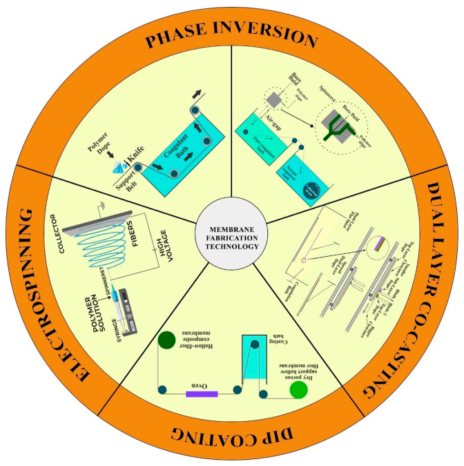
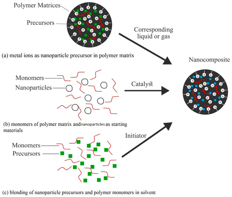
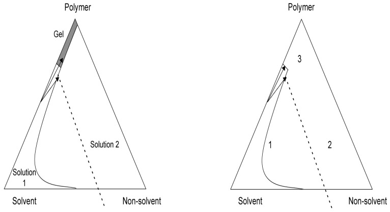
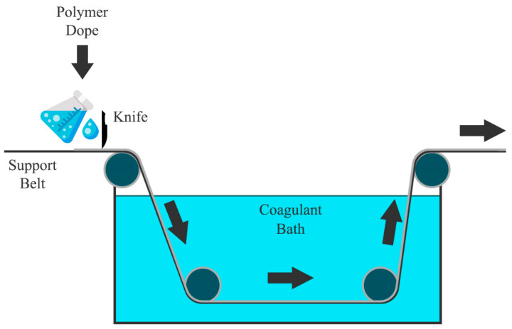
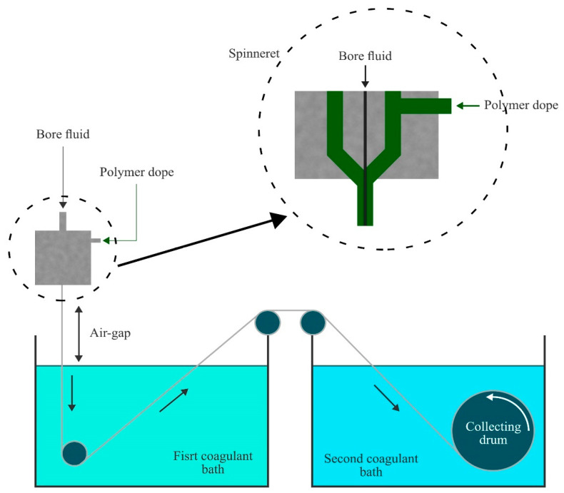
In recent years, technology for the fabrication of mixed-matrix membranes has received significant research interest due to the widespread use of mixed-matrix membranes (MMMs) for various separation processes, as well as biomedical applications. MMMs possess a wide range of properties, including selectivity, good permeability of desired liquid or gas, antifouling behavior, and desired mechanical strength, which makes them preferable for research nowadays. However, these properties of MMMs are due to their tailored and designed structure, which is possible due to a fabrication process with controlled fabrication parameters and a choice of appropriate materials, such as a polymer matrix with dispersed nanoparticulates based on a typical application. Therefore, several conventional fabrication methods such as a phase-inversion process, interfacial polymerization, co-casting, coating, electrospinning, etc., have been implemented for MMM preparation, and there is a drive for continuous modification of advanced, easy, and economic MMM fabrication technology for industrial-, small-, and bulk-scale production. This review focuses on different MMM fabrication processes and the importance of various parameter controls and membrane efficiency, as well as tackling membrane fouling with the use of nanomaterials in MMMs. Finally, future challenges and outlooks are highlighted.

Keywords: MMMs; electrospinning; fabrication; interfacial polymerization; membrane; membrane fouling; mixed-matrix membranes; nanomaterials; phase-inversion process.


Conflict of interest statement

The authors declare no conflict of interest.

Figures

Figure 1
Figure 1
The number of publications each year since 2001 based on the keyword “Mixed matrix membrane” in the Web of Science database (data collected on 7 October 2020).
Figure 2
Figure 2
Schematic representation of various antifouling mechanisms with composite membranes: (a) thin layer of bounded water, (b) electrostatic repulsion, and (c) steric repulsion (adapted with permission from [39]).
Figure 3
Figure 3
UV-photo-grafting setup for hollow-fiber membrane fabrication.
Figure 4
Figure 4
Various membrane-fabrication approaches.
Figure 5
Figure 5
In situ synthesis process of mixed-matrix membranes.
Figure 6
Figure 6
Phase diagram for the phase-inversion process.
Figure 7
Figure 7
Illustration of membrane casting.
Figure 8
Figure 8
Spinning process of hollow-fiber membranes.
Figure 9
Figure 9
Schematic drawing of multi-layer polyelectrolyte deposition on the outer surface of a hollow-fiber membrane (adapted with permission from [185]).
Scheme 1
Scheme 1
Commonly used polyanions and polycations for the development of active–selective layer: Top: polyanions, from left to right: poly(styrene sulfonate) (PSS) sodium salt, poly(acrylic acid) (PAA), sulfated chitosan (S-Ch); Bottom: polycations, from left to right: poly(diallyldimethyl ammonium chloride) (PDADMAC); chitosan(Ch); polyethylenimine (PEI).
Figure 10
Figure 10
Plot of pH and zeta potential of polyelectrolyte (—) and substrate (---); ⚫, iso-electric point of polyelectrolyte; and ○, iso-electric point of substrate (adapted with permission from [196]).
Figure 11
Figure 11
(a) Schematic diagram of a dual-layer hollow-fiber spinning process; (b) cross section of a triple-orifice spinneret (adapted with permission from [201]); and (c) fabrication process of a dual-layer flat-sheet membrane using a double-blade casting machine (adapted with permission from [202]).
Figure 11
Figure 11
(a) Schematic diagram of a dual-layer hollow-fiber spinning process; (b) cross section of a triple-orifice spinneret (adapted with permission from [201]); and (c) fabrication process of a dual-layer flat-sheet membrane using a double-blade casting machine (adapted with permission from [202]).
Figure 12
Figure 12
Hollow-fiber composite membrane fabrication by the dip-coating process.
Figure 13
Figure 13
Schematic diagram of electrospinning setup: (a) horizontal; (b) vertical (adapted with permission from [212]).
Figure 14
Figure 14
Formation of a Taylor cone with the increase of applied voltage.
Figure 15
Figure 15
The number of publications each year since 2001 based on the keyword “Electrospinning” in the Web of Science database (data collected on 20 October 2020).
Figure 16
Figure 16
Scanning electron microscopy image of an electrospun polymer: a poly(acrylonitrile) non-woven nanofiber mat produced by electrospinning (adapted with permission from [221]).
Figure 17
Figure 17
Fabrication of reinforced electrospun scaffolds. Electrospun scaffolds were produced from a 40:60 ratio of PCL:gelatin. The scaffolds were then placed in a 3D printer, and a PLA mesh was deposited onto one side of the scaffold. Two types of 3D-printed meshes were generated: one with a 6 mm distance between PLA struts, and the other with an 8 mm distance between struts (adapted with permission from [274]).
Figure 18
Figure 18
SEM images of reinforced electrospun scaffolds. (AC) SEM images of the electrospun side of the reinforced scaffolds. The images show a uniform distribution of randomly oriented fibers. (DF) SEM images of the 3D-printed side of the scaffolds. The high-magnification images (F) show that there is minimal damage to the electrospun fibers in the immediate vicinity of the 3D-printed PLA mesh. Yellow arrows depict the 3D-printed PLA. White arrowheads depict the PCL:gelatin scaffold (adapted with permission from [274]).

References

    1. Ulbricht M. Advanced functional polymer membranes. Polymer. 2006;47:2217–2262. doi: 10.1016/j.polymer.2006.01.084. - DOI
    1. Narain R. Polymer Science and Nanotechnology: Fundamentals and Applications. Elsevier; San Diego, CA, USA: 2020.
    1. Matin A., Khan Z., Zaidi S., Boyce M. Biofouling in reverse osmosis membranes for seawater desalination: Phenomena and prevention. Desalination. 2011;281:1–16. doi: 10.1016/j.desal.2011.06.063. - DOI
    1. Goh P., Ismail A., Ng B. Carbon nanotubes for desalination: Performance evaluation and current hurdles. Desalination. 2013;308:2–14. doi: 10.1016/j.desal.2012.07.040. - DOI
    1. Baglio V., Arico A., Di Blasi A., Antonucci P., Nannetti F., Tricoli V., Antonucci V. Zeolite-based composite membranes for high temperature direct methanol fuel cells. J. Appl. Electrochem. 2005;35:207–212. doi: 10.1007/s10800-004-6202-z. - DOI

LinkOut - more resources