Review
. 2021 Jul 28;12(8):895.
doi: 10.3390/mi12080895.

Laser Processing of Hard and Ultra-Hard Materials for Micro-Machining and Surface Engineering Applications

Affiliations
Review

Laser Processing of Hard and Ultra-Hard Materials for Micro-Machining and Surface Engineering Applications

Kafayat Eniola Hazzan et al. Micromachines (Basel). .

Abstract

Polycrystalline diamonds, polycrystalline cubic boron nitrides and tungsten carbides are considered difficult to process due to their superior mechanical (hardness, toughness) and wear properties. This paper aims to review the recent progress in the use of lasers to texture hard and ultra-hard materials to a high and reproducible quality. The effect of wavelength, beam type, pulse duration, fluence, and scanning speed is extensively reviewed, and the resulting laser mechanisms, induced damage, surface integrity, and existing challenges discussed. The cutting performance of different textures in real applications is examined, and the key influence of texture size, texture geometry, area ratio, area density, orientation, and solid lubricants is highlighted. Pulsed laser ablation (PLA) is an established method for surface texturing. Defects include melt debris, unwanted allotropic phase transitions, recast layer, porosity, and cracking, leading to non-uniform mechanical properties and surface roughness in fabricated textures. An evaluation of the main laser parameters indicates that shorter pulse durations (ns-fs), fluences greater than the ablation threshold, and optimised multi-pass scanning speeds can deliver sufficient energy to create textures to the required depth and profile with minimal defects. Surface texturing improves the tribological performance of cutting tools in dry conditions, reducing coefficient of friction (COF), cutting forces, wear, machining temperature, and adhesion. It is evident that cutting conditions (feed speed, workpiece material) have a primary role in the performance of textured tools. The identified gaps in laser surface texturing and texture performance are detailed to provide future trends and research directions in the field.

Keywords: cutting tools; laser processing; laser-based micromachining; polycrystalline boron nitride; polycrystalline diamond; surface texturing; tungsten carbide.


Conflict of interest statement

The authors have no conflict of interest to declare that are relevant to the content of this article. All authors have reached agreement for publication.

Figures

Figure 2
Figure 2
(a) Schematic of atomic arrangement, (b) possible formats for polycrystalline materials, adapted from [15].
Figure 4
Figure 4
Typical industrial applications of PCD, PcBN, and WC ([21,32,34,35,36,37]).
Figure 5
Figure 5
(a) Manufacturing stages of cutting tool insert adapted from [29] (copyright permission from Elsevier), (b) Cutting edge preparation by laser machining [30] (copyright permission from Elsevier), (c) Grooved chip breaker design by laser processing [31] (copyright permission from Springer Nature).
Figure 17
Figure 17
Texture dimension distribution based on the literature reviewed in this paper ([32,45,56,57,74,88,90,92,94,95,100,101,103,104,105,106,107,108,110,112,113,115,116,117,118,119,120,121,122,123,124,125,126,127,128,129,130,131,132,133,134,135,136,137,138,139,140,141,142,143,144,145,146,147,148,149]).
Figure 1
Figure 1
Types of hybridisations.
Figure 3
Figure 3
Examples of different material and binder compositions: (a) PCD-Co [8] (copyright permission from Elsevier), (b) PcBN-TiC [17] (copyright permission from Elsevier), (c) WC-Co.
Figure 6
Figure 6
(a) Ablation process, (b) fluence ~ material ablation threshold, (c) fluence >> material ablation threshold.
Figure 7
Figure 7
(a) Overview of material behaviour at different wavelengths, (b) Ablation rate for PCD. (c) Ablation rate for WC [59] (copyright permission from Elsevier).
Figure 8
Figure 8
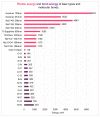
Comparative chart of laser photon energy and bond energy values [67,68,69].
Figure 9
Figure 9
(a) An adapted schematic to compare the effect of pulse duration on a target surface, adapted from [70]. Shock waves are shown by the blue dotted lines. Shorter pulse durations show material expulsion, (b) Electron energy transfer at optical penetration depth compared to thermal depth (11mm for PCD, 5.40 mm for PcBN, 1.2 mm for WC [46]).
Figure 10
Figure 10
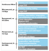
Effect of pulse duration on thermal transition in laser processing PCD (Microsecond, 100–450 μs, nanosecond, 80–125 ns, picosecond 1–10 ps, [44,50,62,82]).
Figure 11
Figure 11
Pulse duration and processing comparison.
Figure 12
Figure 12
Ablative threshold of hard and ultra-hard materials [60,89,90].
Figure 13
Figure 13
(a) Lower fluence compared to higher fluence, (b) Effect of defocusing distance (fluence) on PCD on micro-texture [92] (copyright permission from Elsevier).
Figure 14
Figure 14
(a) Microgrooves on WC-Co at different processing speeds [95] (copyright permission from Trans Tech Publications), (b) CTM302 (PCD), resultant SEM image at different processing speeds: 70 mm/s gives Ra = 0.5 µm, 210 mm/s gives Ra = 0.41 µm [40] (copyright permission from Elsevier).
Figure 15
Figure 15
Micro-texture designs and configurations commonly used: (a) continuous textures, (b) discrete textures, (c) crosshatch features, (d) texture orientation.
Figure 16
Figure 16
Overview comparison of laser parameter selection based on geometry type.
Figure 18
Figure 18
(a) Microgrooves generated on the rake face on turning cutting tool; arrow indicates chip flow direction [162] (copyright permission from Elsevier), (b) Micro-textures on rake face of drill bit (below) [124] (copyright permission from Elsevier).
Figure 19
Figure 19
(A) Linear grooves on rake face, (B) Feed force of micro-textured tools compared to untextured tool after a sliding distance of 2.785 km [100] (copyright permission from Springer Nature).
Figure 20
Figure 20
(a) Types of micro-textures: linear grooves, dimples, rectangular pits, sinusoidal grooves, rhombic grooves, (b) Chip formation from the different texture geometries (right) [103] (copyright permission from the American Society of Mechanical Engineers).
Figure 21
Figure 21
(a) Schematic of elliptical grove textures on rake and flank face, filled with MoS2 adapted from [107], (b) Honey-comb geometry created on a H10S WC tool [135] (copyright permission from MDPI AG).
Figure 22
Figure 22
Wear track on WC rake face at 120 m/min after 150 s cutting with different texture geometries: GT-Grooves, PT-Dimples, GPT-Hybrid texture. Comparison of COF at tool-chip interface [110] (copyright permission from Springer Nature).
Figure 23
Figure 23
(a) Wear of PCD tool—Top flank face and bottom rake face after 2.758 km, (b) Comparison of cutting forces with textured and untextured tool [119] (copyright permission from Elsevier).
Figure 24
Figure 24
(a) Rake face of parallel micro-textured cutting tool on WC after 900 s of machining H-13 steel workpiece, (b) individual mechanical micro-texture groove, (c) front and back edge of texture groove, (d) severe ploughing marks [141] (copyright permission from Elsevier).
Figure 25
Figure 25
Wear mechanism on PcBN textured tools [94] (copyright permission from Elsevier).
Figure 26
Figure 26
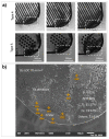
(a) Example of crater wear progression on two of the textures created. Type 4: width 35 μm, spacing 70 μm, depth 10 μm. Type 5: width 60 μm, spacing 150 μm, depth 15 μm, (b) Chip adhesion and crater wear on the rake face of PcBN tool [164] (copyright permission from Elsevier).
Figure 27
Figure 27
(a) Crater wear on cutting tool and BUE adhesion on the dimple texture after a cutting length of 4030 m [125] (copyright permission from Elsevier), (b) Adhesion wear on WC textured surface with W-S-C coating [120] (copyright permission from Elsevier).
Figure 28
Figure 28
Molybdenum disulphide layer structure.
Figure 29
Figure 29
Potential ANN structure to fully describe the laser processing and surface texture performance where 1—Cutting speed, 2—Material property, 3—Surface roughness, 4—Workpiece material, 5—Depth of cut, 6—Texture Density, 7—Area ratio, 8—Width, 9—Depth, 10—Pulse energy, 11 —Laser feed speed, 12—Pulse Duration, 13—Nano-features, 14—Wear, 15—Adhesion, 16—Coefficient of friction.

References

    1. Paul S., Singh R., Yan W. Lasers Based Manufacturin. Springer; New Delhi, India: 2015. - DOI
    1. Wu Z., Bao H., Xing Y., Liu L. Tribological characteristics and advanced processing methods of textured surfaces: A review. Int. J. Adv. Manuf. Technol. 2021;114:1241–1277. doi: 10.1007/s00170-021-06954-2. - DOI
    1. Denyer D., Tranfield D. The SAGE Handbook of Organisational Research Methods. Sage; London, UK: 2009. Producing a systematic review.pdf; pp. 671–689.
    1. Sumiya H., Harano K. Innovative ultra-hard materials: Binderless nanopolycrystalline diamond and nano-polycrystalline cubic boron nitride. SEI Tech. Rev. 2016;82:21–26.
    1. McKie A., Winzer J., Sigalas I., Herrmann M., Weiler L., Rodel J., Can N. Mechanical properties of cBN-Al composite materials. Ceram. Int. 2011;37:1–8. doi: 10.1016/j.ceramint.2010.07.034. - DOI

LinkOut - more resources