Review
. 2021 Aug 18;13(16):2771.
doi: 10.3390/polym13162771.

Carbonaceous Materials Coated Carbon Fibre Reinforced Polymer Matrix Composites

Affiliations
Review

Carbonaceous Materials Coated Carbon Fibre Reinforced Polymer Matrix Composites

Bidita Salahuddin et al. Polymers (Basel). .

Abstract

Carbon fibre reinforced polymer composites have high mechanical properties that make them exemplary engineered materials to carry loads and stresses. Coupling fibre and matrix together require good understanding of not only fibre morphology but also matrix rheology. One way of having a strongly coupled fibre and matrix interface is to size the reinforcing fibres by means of micro- or nanocarbon materials coating on the fibre surface. Common coating materials used are carbon nanotubes and nanofibres and graphene, and more recently carbon black (colloidal particles of virtually pure elemental carbon) and graphite. There are several chemical, thermal, and electrochemical processes that are used for coating the carbonous materials onto a carbon fibre surface. Sizing of fibres provides higher interfacial adhesion between fibre and matrix and allows better fibre wetting by the surrounded matrix material. This review paper goes over numerous techniques that are used for engineering the interface between both fibre and matrix systems, which is eventually the key to better mechanical properties of the composite systems.

Keywords: carbon fibre; carbon nanotube coating; chemical vapor deposition; fibre/matrix interface; graphene coating; mechanical properties; polymer composites.


Conflict of interest statement

The authors declare no conflict of interest.

Figures

Figure 1
Figure 1
(A) TEM images of the carbon nanotubes: I. aligned bundles of hollow-core MWCNTs; II. isolated MWCNTs. (B) Schematic diagram illustrating: I. carbon fibre after the growth of CNTs/CNFs; II. fibre dipped in polymer matrix and drawn through the die to fabricate a single fibre tow composite specimen; III. carbon fibre after drawing through the die showing partial alignment of CNTs/CNFs along the fibre axis due to the viscous force of the matrix and the force due to the smallness of the orifice. Reprinted with permission from ref. [91], Copyright 2011 Elsevier Ltd.
Figure 2
Figure 2
(A) Schematic diagrams of cryogenic testing system for three-point bending and tensile tests. Reprinted from ref. [106], Copyright 1969 Elsevier Ltd. (B) SEM image of GO coated SCFs. Reprinted with permission from ref. [105], Copyright 2016 Elsevier Ltd. (C) SEM images of graphene oxide grafted on CF. Reprinted with permission from ref. [107], Copyright 2020 Elsevier Ltd.
Figure 3
Figure 3
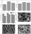
Mechanical properties of carbon black coated CFs/epoxy composites: (A) IFSS tests results of the composites. (B) ILSS of the composites. (C) Impact test results of the composites and single fibre tensile strength. SEM morphologies of the fracture surface of composites (D) the untreated-CF, (E) CF-5 min, (F) CF-10 min. Reprinted with permission from ref. [22], Copyright 2017 Elsevier Ltd.
Figure 4
Figure 4
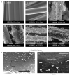
(A) SEM images for the surface of CFs at different applied voltages for 5 min. Reprinted with permission from ref. [112], Copyright 2008 Elsevier Ltd. (B) SEM images: I. composite plate coated with a 2-μm-thick graphite layer; II. composite plate coated with a 50-μm-thick graphite layer. Reprinted with permission from ref. [116], Copyright 2011 Elsevier B.V.
Figure 5
Figure 5
(A) Schematic diagram of a floating catalyst CVD. (B) SEM images of CNT morphology on CF surface as a function of time under 700 °C temperature and 100 mL/min carrier gas flow rate. Reprinted with permission from ref. [117], Copyright 2014 Society of Plastics Engineers.
Figure 6
Figure 6
Schematic illustrations of CNT spray coating. (A) Onto CF prepreg. Reprinted with permission from ref. [121], Copyright 2014 Elsevier Ltd. (B) Onto chopped CFs. Reprinted with permission from ref. [32], Copyright 2019 Elsevier Ltd.
Figure 7
Figure 7
Effect of CNT coating on morphological and mechanical properties of CF reinforced HDPE composites: (A) Fracture morphologies: I. Neat CF/HDPE composite; II. CNT coated CF/HDPE composite. (B) Comparison of tensile strength. (C) Comparison of flexural properties. Reprinted with permission from ref. [32], Copyright 2019 Elsevier Ltd.
Figure 8
Figure 8
Carbon materials and techniques used for CF coating to fabricate polymer composites.

References

    1. Mirabedini A., Ang A., Nikzad M., Fox B., Lau K.T., Hameed N. Evolving strategies for producing multiscale graphene-enhanced fiber-reinforced polymer composites for smart structural applications. Adv. Sci. 2020;7:1903501. doi: 10.1002/advs.201903501. - DOI - PMC - PubMed
    1. Njuguna J. Structural Nanocomposites: Perspectives for Future Applications. Springer Science and Business Media; New York, NY, USA: 2013.
    1. Rajak D.K., Pagar D.D., Menezes P.L., Linul E. Fiber-Reinforced Polymer Composites: Manufacturing, Properties, and Applications. Polymers. 2019;11:1667. doi: 10.3390/polym11101667. - DOI - PMC - PubMed
    1. Soutis C. Carbon fiber reinforced plastics in aircraft construction. Mater. Sci. Eng. A. 2005;412:171–176. doi: 10.1016/j.msea.2005.08.064. - DOI
    1. Lewis S. The use of carbon fibre composites on military aircraft. Compos. Manuf. 1994;5:95–103. doi: 10.1016/0956-7143(94)90060-4. - DOI

LinkOut - more resources