. 2021 Sep 1;28(Pt 5):1343-1356.
doi: 10.1107/S1600577521007931. Epub 2021 Aug 26.

Single-particle cryo-EM: alternative schemes to improve dose efficiency

Affiliations

Single-particle cryo-EM: alternative schemes to improve dose efficiency

Yue Zhang et al. J Synchrotron Radiat. .

Abstract

Imaging of biomolecules by ionizing radiation, such as electrons, causes radiation damage which introduces structural and compositional changes of the specimen. The total number of high-energy electrons per surface area that can be used for imaging in cryogenic electron microscopy (cryo-EM) is severely restricted due to radiation damage, resulting in low signal-to-noise ratios (SNR). High resolution details are dampened by the transfer function of the microscope and detector, and are the first to be lost as radiation damage alters the individual molecules which are presumed to be identical during averaging. As a consequence, radiation damage puts a limit on the particle size and sample heterogeneity with which electron microscopy (EM) can deal. Since a transmission EM (TEM) image is formed from the scattering process of the electron by the specimen interaction potential, radiation damage is inevitable. However, we can aim to maximize the information transfer for a given dose and increase the SNR by finding alternatives to the conventional phase-contrast cryo-EM techniques. Here some alternative transmission electron microscopy techniques are reviewed, including phase plate, multi-pass transmission electron microscopy, off-axis holography, ptychography and a quantum sorter. Their prospects for providing more or complementary structural information within the limited lifetime of the sample are discussed.

Keywords: holography; multi-pass TEM; phase plate; ptychography; quantum sorter.


Figures

Figure 1
Figure 1
Contrast transfer function of (a) conventional TEM at Scherzer defocus, Δf Sch = 87 nm; (b) conventional TEM at defocus, Δf = 1.2 µm; (c) with phase plate at defocus of 0.6Δf Sch = 52 nm with cut-on frequency at 1/25 nm−1; (d) holography at Gábor defocus, Δf Gabor = 49 nm. All have the illumination semi-angle set at 15 µrad.
Figure 2
Figure 2
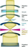
Schematic of a laser phase plate in a TEM. The high-power standing laser wave introduces a phase shift to the unscattered beam. A Lorentz lens after the objective lens is used for magnifying the back focal plane to reduce the constraint of the laser mode waist.
Figure 3
Figure 3
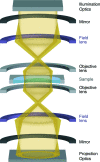
Schematic illustration of the MPTEM setup. The electron beam is generated by the illumination optics, passes through a gated mirror, goes through the sample, and bounces back and forth between the two gated mirrors (shown in black). After having passed through the sample m times, the beam is gated through the second mirror and enters the projection optics and is recorded by the detector.
Figure 4
Figure 4
Schematic illustration of the off-axis electron holography setup. (a) Conventional off-axis electron holography. Half of the beam passes through the specimen (sampling beam) and the other half goes through the vacuum (reference beam). The two beams are next to each other, and the illuminated area can only be at the edge of the sample. Two beams are superimposed by the electron biprism, a positively charged wire, and interfere at the detector plane. (b) Split-illumination holography. The beam is split by condenser biprisms. The reference and sampling beam can go through two neighboring holes of the sample grid.
Figure 5
Figure 5
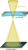
Schematic illustration of cryo-ptychography. A small convergent electron beam scans through the specimen (shown within 1 µm hole) at a certain defocus. A high-speed pixelated detector is used for recording diffractograms that are subsequently collected from partially overlapping sample positions.
Figure 6
Figure 6
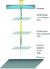
Scheme of the new electro-optical setup allowing optimal discrimination between proteins. An OAM sorter made by three elements performs the Cartesian-polar mapping. Electron vortex beams which contain information hidden in their OAMs are generated after passing through the sample in the specimen plane. The first two holograms (S1, S2) perform the OAM sorting, and the log-polar spectrum is further passed through another hologram (S3) and then through a cylindrical lens (not shown in the figure).
Figure 7
Figure 7
Comparison of the custom basis representation of proteins. The use of the optimized projection permits discrimination between the two models below. It can be appreciated that most of the information is contained in the l = 0 axis and in a restricted set of radial coordinates. Reproduced from Troiani et al. (2020 ▸) with permission from the American Physical Society.

References

    1. Allars, F., Lu, P.-H., Kruth, M., Dunin-Borkowski, R. E., Rodenburg, J. M. & Maiden, A. M. (2021). Ultramicroscopy, https://doi.org/10.1016/j.ultramic.2021.113257. - PubMed
    1. Aoyama, K. & Ru, Q. (1996). J. Microsc. 182, 177–185. - PubMed
    1. Arnaud, J. A. (1969). Appl. Opt. 8, 189. - PubMed
    1. Badde, H. G. & Beimer, L. (1970). Z. Naturforsch. A, 25, 760–765.
    1. Baksh, P. D., Ostrčil, M., Miszczak, M., Pooley, C., Chapman, R. T., Wyatt, A. S., Springate, E., Chad, J. E., Deinhardt, K., Frey, J. G. & Brocklesby, W. S. (2020). Sci. Adv. 6, eaaz3025. - PMC - PubMed

MeSH terms

Substances