. 2021 Sep 6;12(1):5299.
doi: 10.1038/s41467-021-25511-9.

Electronic Floquet gyro-liquid crystal

Affiliations

Electronic Floquet gyro-liquid crystal

Iliya Esin et al. Nat Commun. .

Abstract

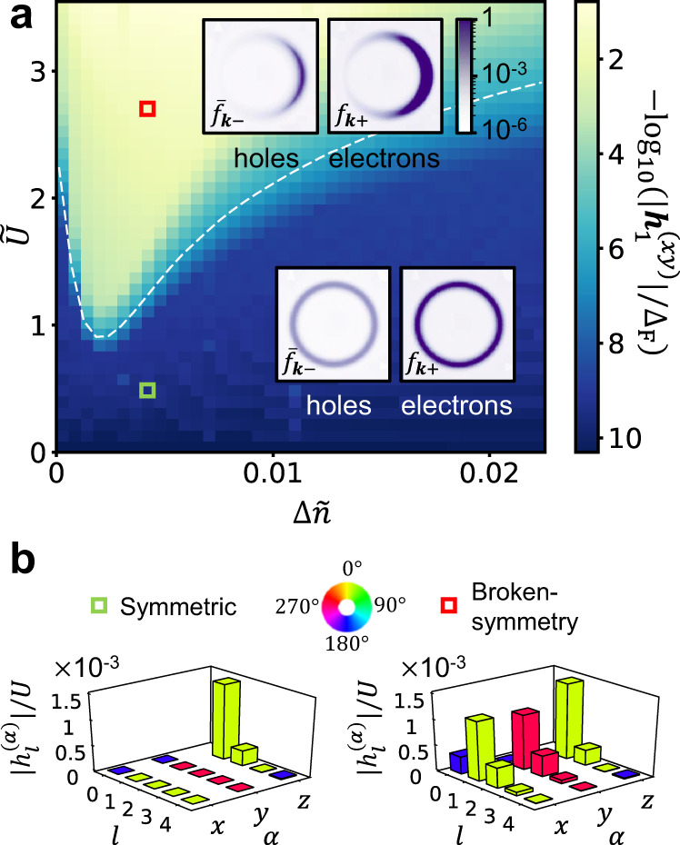
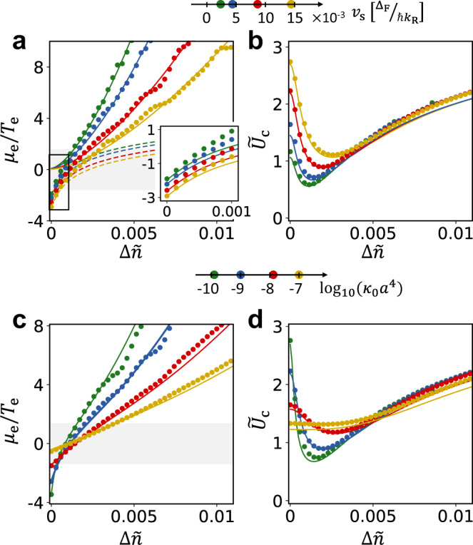
Floquet engineering uses coherent time-periodic drives to realize designer band structures on-demand, thus yielding a versatile approach for inducing a wide range of exotic quantum many-body phenomena. Here we show how this approach can be used to induce non-equilibrium correlated states with spontaneously broken symmetry in lightly doped semiconductors. In the presence of a resonant driving field, the system spontaneously develops quantum liquid crystalline order featuring strong anisotropy whose directionality rotates as a function of time. The phase transition occurs in the steady state of the system achieved due to the interplay between the coherent external drive, electron-electron interactions, and dissipative processes arising from the coupling to phonons and the electromagnetic environment. We obtain the phase diagram of the system using numerical calculations that match predictions obtained from a phenomenological treatment and discuss the conditions on the system and the external drive under which spontaneous symmetry breaking occurs. Our results demonstrate that coherent driving can be used to induce non-equilibrium quantum phases of matter with dynamical broken symmetry.


Conflict of interest statement

The authors declare no competing interests.

Figures

Fig. 1
Fig. 1. Floquet band structure near the Γ-point.
a The band structure of the non-driven semiconductor. The resonance rings of the external drive are indicated by the green curves. b, c Floquet quasienergy bands arising from the semiconductor’s band structure and the resonant drive around ε = 0. The yellow area represents the occupation of the upper Floquet band in the “ideal” distribution scenario, analogous to the zero-temperature Gibbs state for the quasi-energy spectrum. Black arrows represent the pseudospin direction of the Floquet states near the resonance ring. The texture of the pseudospins arises from the pseudospin-momentum locking induced by the semiconductor. In addition, each pseudospin rotates in the x-y plane with the frequency of the periodic drive as is indicated on the figure by the light-gray thin arrows attached to each pseudospin. In the symmetric phase, b due to rotational symmetry, the Floquet states near the resonance ring are uniformly occupied, as is indicated below panel b. Panel c demonstrates the single-particle Floquet bands in the broken symmetry phase. In this case, the resonance ring is tilted towards a spontaneously chosen direction. The occupation of the bands is then biased toward this direction, signaling a ferromagnetic alignment of the pseudospins. d The density of Floquet states as a function of the quasi-energy around ε = 0 in the paramagnetic phase. The density of states features square-root Van Hove singularities in each Floquet band, i.e., DF(δε) ~ δε−1/2 in the upper Floquet band, where δε ≡ ε − ΔF/2. A similar relation holds for the lower Floquet band.
Fig. 2
Fig. 2. Floquet phase diagram.
a Spontaneous magnetization strength, h1(xy), obtained from the self-consistent mean-field calculation, as a function of a normalized electron doping, Δn~Δn/AR and normalized interaction strength, U~ARU/δE. The dashed white line represents the phase boundary, corresponding to the critical interaction strength U~c, calculated from Eq. (10). The insets show the electron and hole steady-state distributions (respectively fk+ and f¯k1fk) in the momentum domain near the resonance ring, for Δn~=0.004, U~=0.44, indicated by a green square, in the symmetric phase, and Δn~=0.004, U~=2.66, indicated by a red square, in the symmetry-broken phase. b Harmonics of the self-consistent magnetization h(t)=Rel,αe^αhl(α)eilΩt, where e^α=x^,y^,z^. We plot hl(α)/U corresponding to the first five harmonics (l = 0, 1, 2, 3, 4) at the two points on the phase diagram indicated by the red and green squares in panel a. The heights and the colors of the bars respectively indicate the amplitudes and phases of the harmonics. The color scale for the phase is shown at the top of the panel. Note that we omit h0(z), which is responsible for the bandgap renormalization of the system in the absence of the drive, see main text.
Fig. 3
Fig. 3. Phase boundary and crossover from EFM to EFI regimes.
a Numerically obtained ratio of effective chemical potential to temperature of the electronic population in the upper Floquet band, as a function of the normalized doping (data points). The data are extracted from the steady-state solution to Eq. (4) for κ0a4 ≈ 10−9 and four values of speed of sound, vs. Solid and dashed lines represent the results of the extended rate equation treatment for the EFM and the EFI phases, respectively. The full set of curves is generated using the same value of the single fit parameter ζ (see text for definition). The shaded area indicates the EFI-to-EFM crossover range where the Θ~-function in Eq. (10) rises from 0 to 1. Inset: Zoom-in on the low-doping regime (enclosed by a black frame in the main panel). Solid lines correspond to the analytical curves for the EFI phase. b Critical interaction strength Uc extracted for the same data set as in panel a (data points). Solid lines represent Uc calculated from Eq. (10), where for the values of μe/Te we used a function that interpolates between the analytical results deep in the EFM and EFI phases. We use the same value of ζ as in panel a, and two additional fitting parameters U~ex and U~fb. c, d Results for μe/Te and Uc, extracted in the same manner as in panels a and b (data points), for vs = 0.0086 ΔF/ℏkR, and four values of κ0. Solid lines in the two panels show the interpolated values of μe/Te and the resulting Uc. All fitting parameters are the same as in panels a and b.

References

    1. Thouless DJ. Quantization of particle transport. Phys. Rev. B. 1983;27:6083. doi: 10.1103/PhysRevB.27.6083. - DOI
    1. Nakajima S, et al. Topological Thouless pumping of ultracold fermions. Nat. Phys. 2016;12:296. doi: 10.1038/nphys3622. - DOI
    1. Lohse M, Schweizer C, Zilberberg O, Aidelsburger M, Bloch I. A Thouless quantum pump with ultracold bosonic atoms in an optical superlattice. Nat. Phys. 2016;12:350. doi: 10.1038/nphys3584. - DOI
    1. Lindner NH, Berg E, Rudner MS. Universal chiral quasisteady states in periodically driven many-body systems. Phys. Rev. X. 2017;7:011018.
    1. Sacha K. Modeling spontaneous breaking of time-translation symmetry. Phys. Rev. A. 2015;91:033617. doi: 10.1103/PhysRevA.91.033617. - DOI