Review
. 2021 Oct;18(5):329-344.
doi: 10.1007/s11897-021-00528-9. Epub 2021 Sep 8.

Optimal CRT Implantation-Where and How To Place the Left-Ventricular Lead?

Affiliations
Review

Optimal CRT Implantation-Where and How To Place the Left-Ventricular Lead?

Christian Butter et al. Curr Heart Fail Rep. 2021 Oct.

Abstract

Purpose of review: Cardiac resynchronization therapy (CRT) represents a well-established and effective non-pharmaceutical heart failure (HF) treatment in selected patients. Still, a significant number of patients remain CRT non-responders. An optimal placement of the left ventricular (LV) lead appears crucial for the intended hemodynamic and hence clinical improvement. A well-localized target area and tools that help to achieve successful lead implantation seem to be of utmost importance to reach an optimal CRT effect.

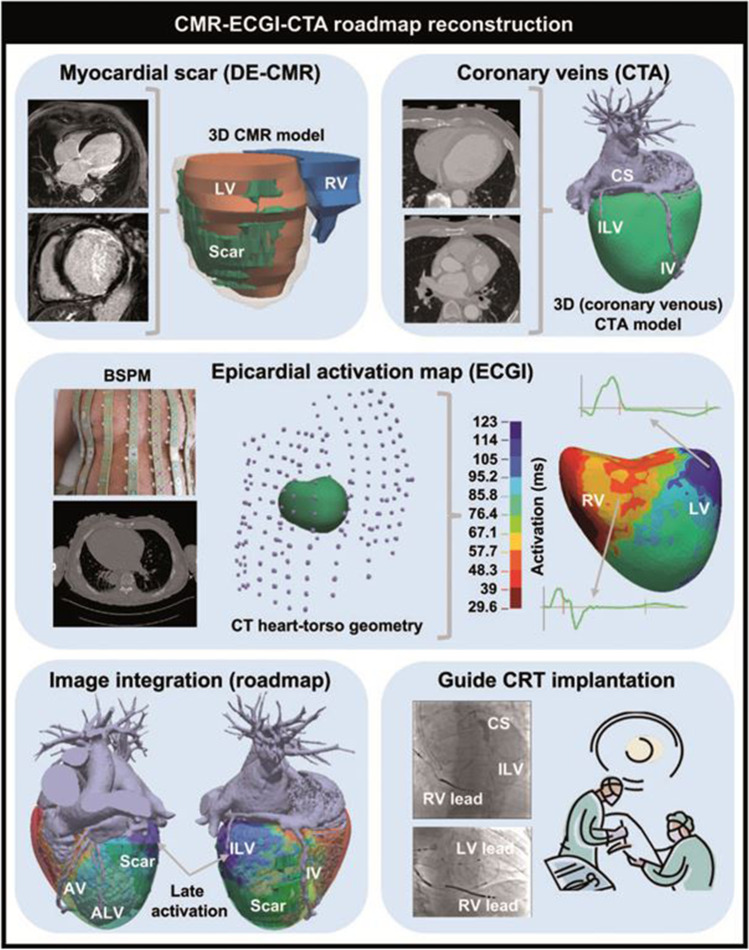
Recent findings: Recent studies suggest previous multimodal imaging (CT/cMRI/ECG torso) to guide intraprocedural LV lead placement. Relevant benefit compared to empirical lead optimization is still a matter of debate. Technical improvements in leads and algorithms (e.g., multipoint pacing (MPP), adaptive algorithms) promise higher procedural success. Recently emerging alternatives for ventricular synchronization such as conduction system pacing (CSP), LV endocardial pacing, or leadless pacing challenge classical biventricular pacing. This article reviews current strategies for a successful planning, implementation, and validation of the optimal CRT implantation. Pre-implant imaging modalities offer promising assistance for complex cases; empirical lead positioning and intraoperative testing remain the cornerstone in most cases and ensure a successful CRT effect.

Keywords: Acute hemodynamic response; Cardiac resynchronization therapy; Coronary sinus; Lead implantation; Multimodal imaging.


Conflict of interest statement

The authors declare no competing interests.

Figures

Fig. 1
Fig. 1
CMR–ECGi–CTA roadmap reconstruction [25]. Workflow for CMR-ECGI-CTA roadmap reconstruction for CRT implantation guidance. AV, anterior vein; BSPM, body surface potential measurement; CMR, cardiac magnetic resonance imaging; CS, coronary sinus; CTA, computed tomography angiography; DE-CMR, delayed enhancement cardiac magnetic resonance imaging; ECGI, electrocardiographic imaging; ILV, inferolateral vein; IV, inferior vein; LV, left ventricle; RV, right ventricle
Fig. 2
Fig. 2
Proportion of CRT patients and reasonable diagnostic effort. The majority of CRT-eligible patients can be treated adopting a general approach. For selected patients and complex cases, an individualized approach using pre-implant imaging or invasive hemodynamic optimization is needed. cMR, cardiac magnetic resonance; EAM, electroanatomical mapping
Fig. 3
Fig. 3
Angiographic classification of the cardiac venous anatomy in LAO (a, b) and RAO (c) projection. CS, coronary sinus; GV, great cardiac vein; AL, anterolateral vein; LV, lateral vein; PV, posterior vein; AV, anterior vein
Fig. 4
Fig. 4
Acute hemodynamic effects of free wall (Fwl) and anterior (Ant) pacing [31]. A Scatter plot comparing %dP/dtmax with Fwl and Ant stimulation. Each point (n = 30) is the response for 1 patient at the optimum AV delay. Symbols represent individual patients who experienced a significant (♢) or non-significant (♦) difference between Fwl and Ant stimulation response. Points above the identity line (dashed) have a larger Fwl stimulation response. B Summary data demonstrating significant LV + dP/dtmax benefit of Fwl versus Ant stimulation for all patients (n = 30, P < 0.001)
Fig. 5
Fig. 5
Coronary sinus anatomy and Q-LV intervals at different pacing sites [40]. In a 59-year-old man with non-ischemic cardiomyopathy, New York Heart Association Class III, chronic atrial fibrillation, left ventricular (LV) ejection fraction 20%, left bundle branch block, and QRS 180 ms, 4 veins and 8 pacing sites were tested. A Venous angiography. B Schematic representation of the venous anatomy and pacing sites. C Q-LV measurements and increase in LV dP/dtmax are displayed for 7 available pacing sites (site no. 4 was discarded owing to elevated pacing threshold). D Correlation between percentage increase in LV dP/dtmax and Q-LV interval. E Correlation between percentage increase in LV dP/dtmax and QRS narrowing
Fig. 6
Fig. 6
Fluoroscopic implantation images (AG). AC Venous valve at the mid-coronary sinus region (“Vieussens valve”), completely obstructing retrograde contrast flow (A, blue arrow indicates the valve; white arrow, guiding catheter tip). Introduction of a thin sub-selective catheter (red arrow, wire already retracted, also note the retraction of the guiding catheter), enabling cannulation beyond the valve (B) and definition of a suitable side branch anatomy for LV lead placement (C). D Ostial (“Thebesian”) coronary venous valve (white arrow). E Extended coronary sinus dissection after attempting to overcome a Vieussens valve obstruction with the catheter tip placed distally and ungentle wire advancement. F, G Left bundle branch lead placement in LAO view. The left panel (F) shows a small contrast injection defining the septal endocardium at the tip of the 3D implantation catheter distal and caudal to the His region (indicated by the quadripolar EP catheter). The right panel (G) shows deep septal implantation of a Medtronic 3830 SelectSecure™ lumenless pacing lead
Fig. 7
Fig. 7
Schematic representation of pitfalls during LV lead implantation. Carelessly advancing sheaths over the Vieussens valve or accidental balloon occlusion in the Vein of Marshall may cause CS dissection

References

    1. Cazeau S, Leclercq C, Lavergne T, Walker S, Varma C, Linde C, et al. Effects of multisite biventricular pacing in patients with heart failure and intraventricular conduction delay. N Engl J Med. 2001;344(12):873–880. doi: 10.1056/NEJM200103223441202. - DOI - PubMed
    1. Mower M. Method and apparatus for treating hemodynamic dysfunction by simultaneous pacing of both ventricles. US Patent #4,928,688, 29 May 1990.
    1. Daubert C, Behar N, Martins RP, Mabo P, Leclercq C. Avoiding non-responders to cardiac resynchronization therapy: a practical guide. Eur Heart J. 2017;38(19):1463–1472. doi: 10.1093/eurheartj/ehw270. - DOI - PubMed
    1. Pothineni NVK, Supple GE. Navigating challenging left ventricular lead placements for cardiac resynchronization therapy. J Innov Card Rhythm Manag. 2020;11(5):4107–4117. doi: 10.19102/icrm.2020.110505. - DOI - PMC - PubMed
    1. Writing C, Maddox TM, Januzzi JL, Jr, Allen LA, Breathett K, Butler J, et al. 2021 Update to the 2017 ACC expert consensus decision pathway for optimization of heart failure treatment: answers to 10 pivotal issues about heart failure with reduced ejection fraction: a report of the American College of Cardiology Solution Set Oversight Committee. J Am Coll Cardiol. 2021;77(6):772–810. doi: 10.1016/j.jacc.2020.11.022. - DOI - PubMed