. 2022 Jan 1;480(1):191-205.
doi: 10.1097/CORR.0000000000001923.

A Modeling Study of a Patient-specific Safe Zone for THA: Calculation, Validation, and Key Factors Based on Standing and Sitting Sagittal Pelvic Tilt

Affiliations

A Modeling Study of a Patient-specific Safe Zone for THA: Calculation, Validation, and Key Factors Based on Standing and Sitting Sagittal Pelvic Tilt

Hao Tang et al. Clin Orthop Relat Res. .

Abstract

Background: Lumbar-pelvic stiffness and sagittal imbalance have been reported to increase the risk of dislocation and wear after THA. One potential way to approach this concern is by identifying patient-specific safe zones for THA components based on the standing and sitting sagittal pelvic tilt. However, there is no algorithm to integrate the standing and sitting pelvic tilt into the surgical plan of component orientations.

Questions/purposes: We established a new mathematical algorithm for determining a patient-specific safe zone for THA by integrating the impingement-free ROM requirements of standing and sitting while preventing edge loading while standing. We aimed to determine (1) the accuracy of this new method for predicting the impingement-free ROM for a given component orientation, (2) the sensitivity and specificity of detecting an impingement-free acetabular cup position for standing and sitting, and (3) the influences of key factors including pelvic tilt while standing and pelvic tilt while sitting and implant parameters on patient-specific safe zones.

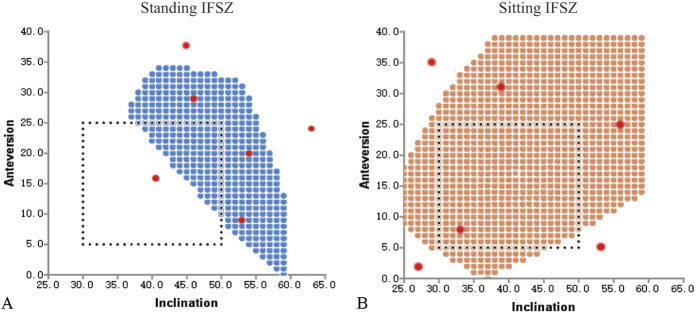
Methods: A strategy for calculating the intersection of standing and sitting impingement-free safe zones and the zone of a standing radiographic inclination of ≤ 45° was used to develop patient-specific safe zones. We conducted a computer simulation study including the pelvis and THA prosthesis to answer the three study questions. We enrolled 10 patients who underwent robot-assisted THA for avascular necrosis of the femoral head (mean age 49 ± 19 years; five were women) from October 2019 to December 2019. We used a prosthesis model with a conical stem neck and a non-hooded liner, with the femoral head diameter ranging between 28 mm and 40 mm, and the corresponding head-neck ratio ranging between 2.33 and 3.33. We tested 1680 movements for the accuracy of impingement-free ROM (Question 1), and 80 marginal points and 120 non-marginal points of the comprehensive impingement-free safe zone, which combines the standing and sitting postures (Question 2). For Question 3, we explored the influences of standing and sitting pelvic tilt, femoral head diameter, and ROM criteria on the size of the patient-specific safe zone.

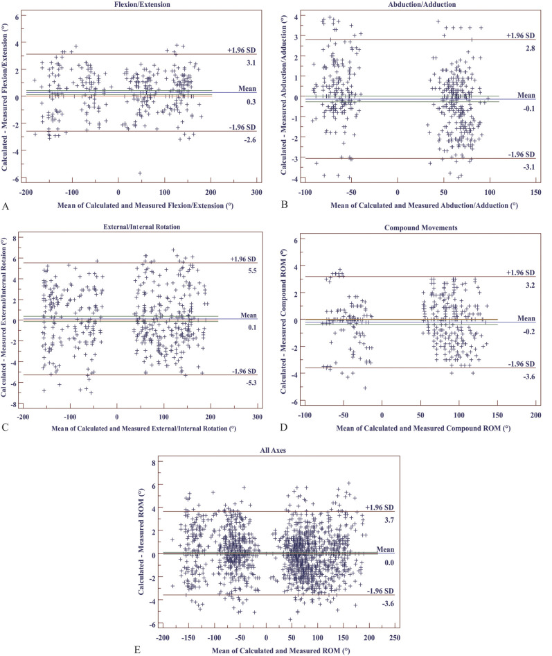
Results: With the simulation method as a reference for detecting impingement, the mean absolute error (arithmetic mean of all the absolute errors) of the calculated impingement-free ROM was 1.4° ± 2.3°, and the limit of agreement of errors was between -3.6° and 3.7°. The sensitivity of detecting a safe cup orientation within the comprehensive impingement-free safe zone for a given ROM criterion was 98.9% (95% CI 93.6% to 99.9%), and specificity was 97.1% (95% CI 91.0% to 99.2%). There were no impingement-free safe zones for 29% (pelvic tilt combinations without an impingement-free safe zone and all tested combinations) and no patient-specific safe zones for 46% (pelvic tilt combinations without a patient-specific safe zone and all tested combinations) of the tested combinations of standing and sitting pelvic tilt. The patient-specific safe zone was sensitive to changes in standing and sitting pelvic tilt, femoral head diameter, stem version, and ROM criteria. Stem anteversions beyond 10° to 20° dramatically reduced the size of the patient-specific safe zone to 0 within a change of 10° to 20°.

Conclusion: The patient-specific safe zone algorithm can be an accurate method for determining the optimal orientation for acetabular cups and femoral stems in THA. The patient-specific safe zone is sensitive to changes in standing and sitting pelvic tilt, stem version, ROM criteria, and the femoral head diameter. A narrow zone of 10° to 20° for stem anteversion is recommended to maximize the size of the patient-specific safe zone.

Clinical relevance: This study suggests the potential of a mathematical algorithm to optimize the orientation of THA components and illustrates how key parameters affect the patient-specific safe zone.


Conflict of interest statement

Each author certifies that there are no funding or commercial associations (consultancies, stock ownership, equity interest, patent/licensing arrangements, etc.) that might pose a conflict of interest in connection with the submitted article related to the author or any immediate family members. All ICMJE Conflict of Interest Forms for authors and Clinical Orthopaedics and Related Research® editors and board members are on file with the publication and can be viewed on request.

Figures

Fig. 1
Fig. 1
This flowchart shows the study design. PSSZ = patient-specific safe zone. A color image accompanies the online version of this article.
Fig. 2
Fig. 2
These drawings show the pelvic coordinate system, order of movement, and algorithm for detecting impingement. (A) The femoral coordinate system and pelvic coordinate system are shown. (B) In the first step, internal and external rotation around the z-axis of the femur are determined. (C) In the second step, abduction and adduction around the y-axis of the femur are determined. (D) In the third step, flexion and extension around the x-axis of the pelvis are determined. (E) This diagram shows the algorithm for detecting impingement, with R1 as the radius of the femoral head, R2 as the radius of the prosthetic stem neck at the level of impingement, angle A as the technical ROM of the prosthesis, and θ as the femoral position angle between the central axes of the stem neck and the acetabular cup. A color image accompanies the online version of this article.
Fig. 3
Fig. 3
This schematic drawing illustrates the algorithm for calculating the impingement-free safe zone. The cup orientation is judged to be safe if the calculated impingement-free ROM fulfills the ROM criteria (Table 2) in both the (A) standing position and (B) sitting position. A color image accompanies the online version of this article.
Fig. 4
Fig. 4
This figure shows the algorithm for calculating the patient-specific safe zone. (A) A full-length standing lateral image was used to obtain a standing pelvic tilt value, which was imputed into the formula to calculate (B) the standing impingement-free safe zone (IFSZ). (C) A full-length sitting lateral image was similarly used to determine (D) the sitting impingement-free safe zone. The standing and sitting impingement-free safe zones were integrated to obtain the intersection and form (E) the comprehensive impingement-free safe zone. (F) A zone with a standing radiographic inclination of ≤ 45° was maintained to form the patient-specific safe zone (PSSZ). Pelvic incidence is defined as the angle between the line connecting the midpoint of the bilateral femoral head’s center and the midpoint of the S1 endplate and the line perpendicular to the S1 upper endplate. The prosthesis model included in this figure was a 36-mm-diameter femoral head with other parameters identical to that in Table. 2.
Fig. 5
Fig. 5
The CAD model for the validation experiment is shown. (A) Impingement was detected by simulated 53° of extension, 0° of internal rotation, and 0° of abduction. (B) The anterior pelvic plane was determined by the bilateral anterior superior iliac spine and the pubic symphysis; the radiographic anteversion and radiographic inclination were defined based on the orthogonal coordinate system using the anterior pelvic plane as the coronal plane. The stem position had a compound-axis movement with 30° of internal rotation, 30° of adduction, and 93° of flexion, and single-axis movement with 0° of internal rotation, 58° of abduction, and 0° of flexion. A color image accompanies the online version of this article.
Fig. 6
Fig. 6
The design of the impingement-free ROM validation experiment is shown. (A) The standing-position impingement-free safe zone was calculated, and three points within and three points outside (red dots) the impingement-free Safe Zone (blue dots) were randomly selected for examining the accuracy of the impingement-free ROM algorithm for the standing position for corresponding single-axis and compound-axis movement. (B) Six points (red dots) were similarly selected for the sitting-position impingement-free safe zone (orange dots) for examining the algorithm for the sitting position. A color image accompanies the online version of this article.
Fig. 7
Fig. 7
The design of the comprehensive impingement-free safe zone validation experiment is shown. (A) Ten points within the comprehensive impingement-free safe zone (blue dots) were chosen, with four marginal points (yellow dots) and six non-marginal points (red dots) to assess the sensitivity. (B) Ten points outside the comprehensive impingement-free safe zone (blue dots) were similarly chosen, with four marginal points (yellow dots) immediately adjacent to the margins of the comprehensive impingement-free safe zone (blue dots) and six non-marginal points (red dots) to assess the specificity. A color image accompanies the online version of this article.
Fig. 8
Fig. 8
This figure shows the results of the Bland-Altman analysis of the accuracy of the ROM predicted by the impingement-free ROM algorithm, including (A) single-axis movement of flexion and extension, (B) single-axis movement of abduction and adduction, (C) single-axis movement of external and internal rotation, (D) compound movement with three axes involved, and (E) accuracy for all movements. The green line represents the CI of the mean of difference line, and the orange represents the zero line.
Fig. 9
Fig. 9
The influences of PTstanding and PTsitting on the impingement-free safe zone and the patient-specific safe zone are shown, including (A) the influence of PTstanding on the comprehensive impingement-free safe zone with PTsitting set constant at 30°; (B) the influence of PTsitting on the comprehensive impingement-free safe zone with PTstanding set constant at 10°, with each different color showing a cross-section of the three-dimensional space of the safe zone; (C) the influences of PTstanding and PTsitting on the size of the comprehensive impingement-free safe zone; (D) the influences of PTstanding and PTsitting on the size of the patient-specific safe zone, with the red color indicating large size of safe zone and the blue color indicating the small size of safe zone; (E) the influences of PTstanding with different PTsitting values on the size of the impingement-free safe zone; and (F) the influence of PTsitting with different PTstanding values on the size of the impingement-free safe zone. PTstanding = pelvic tilt in the standing position; PTsitting = pelvic tilt in the sitting position.
Fig. 10
Fig. 10
This figure shows the influence of stem version on the impingement-free safe zone and patient-specific safe zone. (A) Excessively small or large stem anteversion reduces the size of the impingement-free safe zone and patient-specific safe zone. The size of the patient-specific safe zone is sensitive to stem version for different (B) PTstanding values and (C) PTsitting values, and there is a zone between 10° and 20° of stem anteversion at which the patient-specific safe zone size is maximized. PTstanding = pelvic tilt in the standing position; PTsitting = pelvic tilt in the sitting position. A color image accompanies the online version of this article.
Fig. 11
Fig. 11
This figure shows the influences of the ROM criteria and femoral head diameter on the patient-specific safe zone. The four ROM criteria gradually decreased for the ROM required for single-axis movement for both standing and sitting, and the compound-axis movement remained the same, as shown in Table 2. A color image accompanies the online version of this article.

Comment in

Similar articles

Cited by

References

    1. Abdel MP, von Roth P, Jennings MT, Hanssen AD, Pagnano MW. What safe zone? The vast majority of dislocated THAs are within the Lewinnek safe zone for acetabular component position. Clin Orthop Relat Res. 2016;474:386-391. - PMC - PubMed
    1. Brown TD, Callaghan JJ. Impingement in total hip replacement: mechanisms and consequences. Curr Orthop. 2008;22:376-391. - PMC - PubMed
    1. Brown TD, Elkins JM, Pedersen DR, Callaghan JJ. Impingement and dislocation in total hip arthroplasty: mechanisms and consequences. Iowa Orthop J. 2014;34:1-15. - PMC - PubMed
    1. Callanan MC, Jarrett B, Bragdon CR, et al. The John Charnley Award: risk factors for cup malpositioning: quality improvement through a joint registry at a tertiary hospital. Clin Orthop Relat Res. 2011;469:319-329. - PMC - PubMed
    1. Crowninshield RD, Maloney WJ, Wentz DH, Humphrey SM, Blanchard CR. Biomechanics of large femoral heads: what they do and don't do. Clin Orthop Relat Res. 2004;429:102-107. - PubMed

Publication types