. 2021 Aug 30;21(17):5853.
doi: 10.3390/s21175853.

A Redundant Configuration of Four Low-Cost GNSS-RTK Receivers for Reliable Estimation of Vehicular Position and Posture

Affiliations

A Redundant Configuration of Four Low-Cost GNSS-RTK Receivers for Reliable Estimation of Vehicular Position and Posture

Jesús Morales et al. Sensors (Basel). .

Abstract

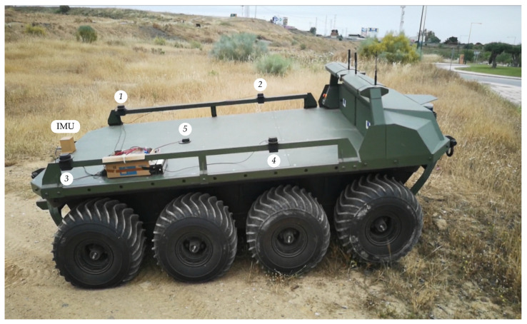
This paper proposes a low-cost sensor system composed of four GNSS-RTK receivers to obtain accurate position and posture estimations for a vehicle in real-time. The four antennas of the receivers are placed so that every three-antennas combination is optimal to get the most precise 3D coordinates with respect to a global reference system. The redundancy provided by the fourth receiver allows to improve estimations even more and to maintain accuracy when one of the receivers fails. A mini computer with the Robotic Operating System is responsible for merging all the available measurements reliably. Successful experiments have been carried out with a ground rover on irregular terrain. Angular estimates similar to those of a high-performance IMU have been achieved in dynamic tests.

Keywords: GNSS receivers; RTK corrections; sensor redundancy; vehicle localization.


Conflict of interest statement

The authors declare no conflict of interest.

Figures

Figure 1
Figure 1
Optimal antenna configuration with three receivers.
Figure 2
Figure 2
Optimal antenna configuration with four receivers.
Figure 3
Figure 3
Redundant antenna configuration with four receivers.
Figure 4
Figure 4
Placement of the antennas on the roof of a car.
Figure 5
Figure 5
Hardware components of the sensor system: a GNSS-RTK board (a), an antenna (b), a ground plate (c) and the mini computer (d).
Figure 6
Figure 6
ROS computation graph with nodes (ellipses) and topics.
Figure 7
Figure 7
The rover Argo XTR with the sensor system mounted on the rear deck. GNSS antennas are numbered from 1 to 5.
Figure 8
Figure 8
Estimation of position coordinates during the reliability test.
Figure 9
Figure 9
Estimation of posture coordinates during the reliability test.
Figure 10
Figure 10
Accuracy estimation during the reliability test.
Figure 11
Figure 11
Aerial view of the path followed by the rover on the countryside.
Figure 12
Figure 12
Comparison between the position coordinates obtained by the fifth receiver and the proposed sensor.
Figure 13
Figure 13
Comparison between the posture coordinates obtained by the IMU and the proposed sensor.

References

    1. Henkel P. Calibration of magnetometers with GNSS receivers and magnetometer-aided GNSS ambiguity fixing. Sensors. 2017;17:1324. doi: 10.3390/s17061324. - DOI - PMC - PubMed
    1. Ahmad N., Ariffin R., Ghazilla R., Khairi N.M., Kasi V. Reviews on various Inertial Measurement Unit (IMU) sensor applications. Int. J. Signal Proc. Syst. 2013;1:256–262. doi: 10.12720/ijsps.1.2.256-262. - DOI
    1. Borenstein J., Everett H.R., Feng L., Wehe D. Mobile robot positioning: Sensors and techniques. J. Robot. Syst. 1997;14:231–249. doi: 10.1002/(SICI)1097-4563(199704)14:4<231::AID-ROB2>3.0.CO;2-R. - DOI
    1. Hein G.W. Status, perspectives and trends of satellite navigation. Satell. Navig. 2020;1:1–12. doi: 10.1186/s43020-020-00023-x. - DOI - PMC - PubMed
    1. Ciecko A., Bakula M., Grunwald G., Cwiklak J. Examination of multi-receiver GPS/EGNOS positioning with Kalman filtering and validation based on CORS stations. Sensors. 2020;20:2732. doi: 10.3390/s20092732. - DOI - PMC - PubMed

LinkOut - more resources