. 2021 Mar 20;8(3):333-343.
doi: 10.1364/optica.414206. Epub 2021 Mar 11.

In-vivo sub-diffraction adaptive optics imaging of photoreceptors in the human eye with annular pupil illumination and sub-Airy detection

Affiliations

In-vivo sub-diffraction adaptive optics imaging of photoreceptors in the human eye with annular pupil illumination and sub-Airy detection

Rongwen Lu et al. Optica. .

Abstract

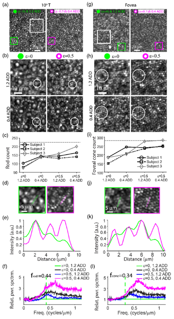
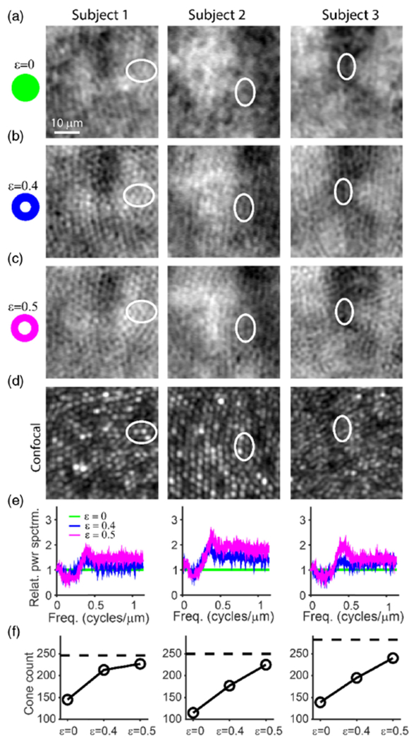
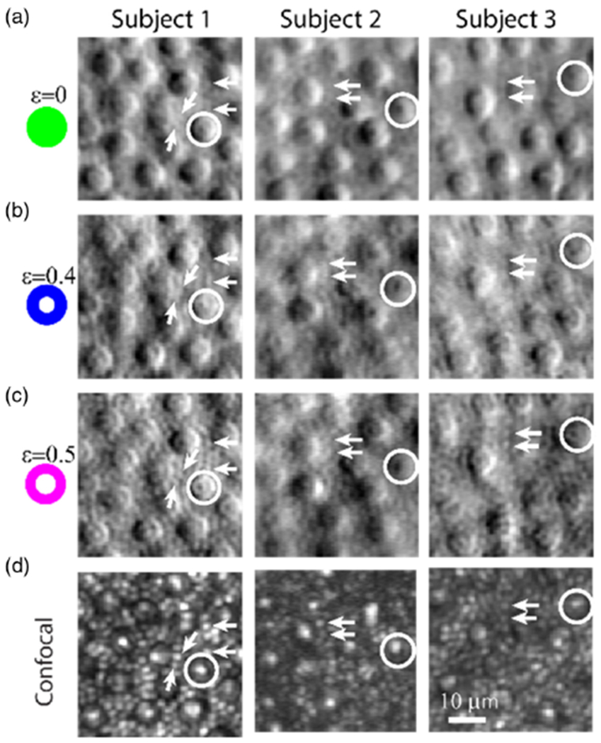
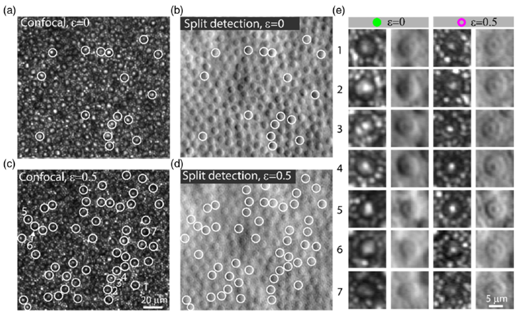
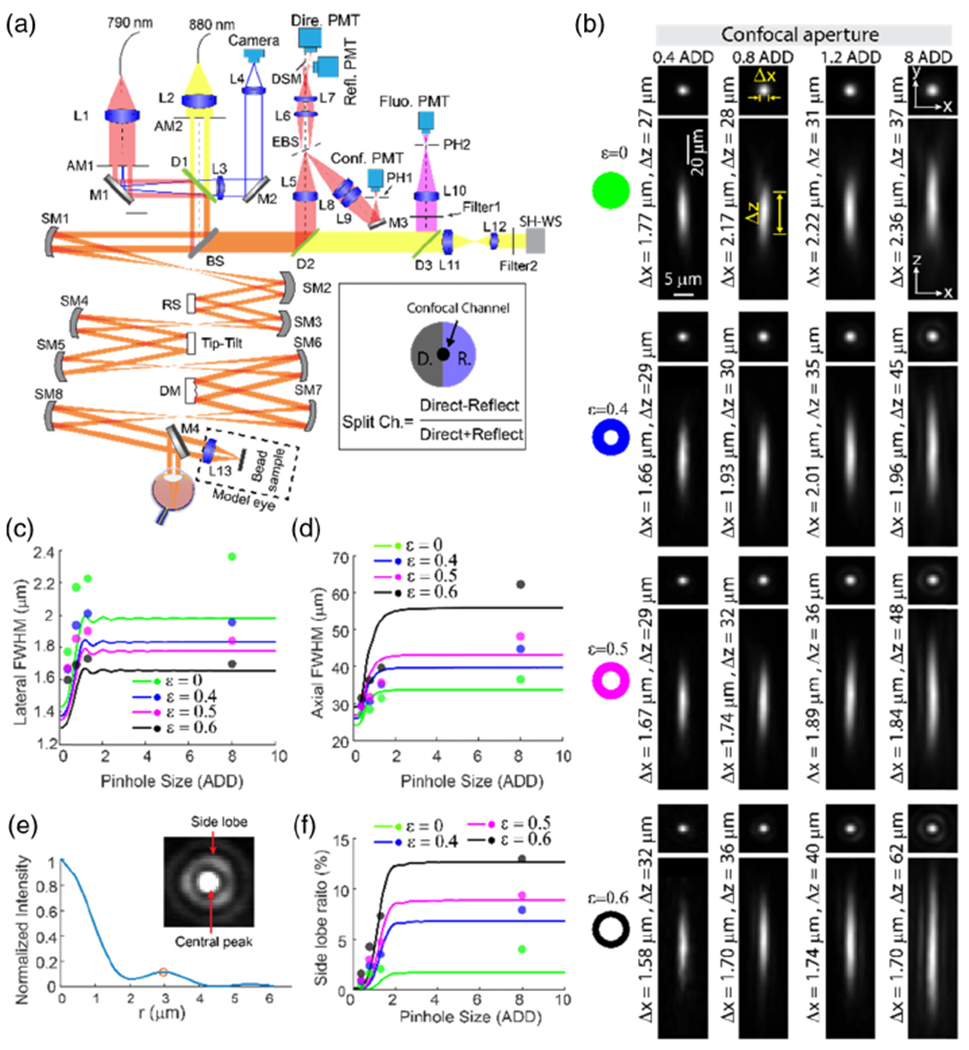
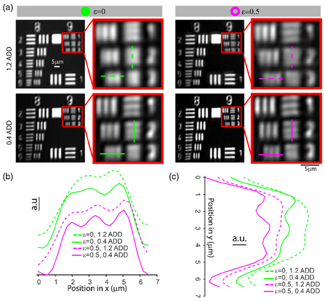
Adaptive optics scanning light ophthalmoscopy (AOSLO) allows non-invasive visualization of the living human eye at the microscopic scale; but even with correction of the ocular wavefront aberrations over a large pupil, the smallest cells in the photoreceptor mosaic cannot always be resolved. Here, we synergistically combine annular pupil illumination with sub-Airy disk confocal detection to demonstrate a 33% improvement in transverse resolution (from 2.36 to 1.58 μm) and a 13% axial resolution enhancement (from 37 to 32 μm), an important step towards the study of the complete photoreceptor mosaic in heath and disease. Interestingly, annular pupil illumination also enhanced the visualization of the photoreceptor mosaic in non-confocal detection schemes such as split detection AOSLO, providing a strategy for enhanced multimodal imaging of the cone and rod photoreceptor mosaic.


Conflict of interest statement

Disclosures. The authors declare no conflict of interests.

Figures

Fig. 1.
Fig. 1.
Rod photoreceptors and foveal cones are improved in confocal reflectance images. Confocal AO images of photoreceptors in the living human eye at retinal locations of (a)–(f) 10° temporal (T) from the locus of fixation and (g)–(l) at the fovea. (a) and (g) Comparison of confocal images sequentially acquired using either (left) full pupil illumination (ε, inner diameter/outer diameter, = 0) and 1.2 Airy disk diameter (ADD) confocal pinhole detection or (right) annular pupil illumination (ε = 0.5) and sub-ADD (0.4 ADD) confocal pinhole detection. The asterisk in (g) denotes the foveal center (estimated based on highest cone density). (b) and (h) Comparison of four imaging conditions: ε = 0 (full pupil illumination) and 1.2 ADD confocal pinhole detection, ε = 0 and 0.4 ADD, ε = 0.5 and 1.2 ADD, and ε = 0.5 and 0.4 ADD. The locations of images in (b) and (h) are specified by the white squares in (a) and (g), respectively. (c) and (i) The total number of rods and foveal cones that could be identified using each modality, respectively, within a 43 μm × 43 μm region of interest (ROI) from three subjects. The horizontal dashed lines in (c) and (i) indicate the expected normal histologic numbers [1] of (c) rods and (i) foveal cones within a 43 μm × 43 μm ROI at retinal locations of 10° T from fixation and 50 μm temporal from the point of the highest density. The actual locations of the foveal ROIs were 40, 42, and 0 μm away from the location corresponding to peak cone density for Subjects 1, 2, and 3, respectively. (d) and (j) Zoom of green and magenta squares in (a) and (g), respectively. (e) and (k) Intensity profiles along green and magenta dashed lines in (d) and (j), respectively. (f) and (l) Relative power spectrum ratio. All retinal images shown here are from Subject 1. Images from all subjects are shown in Figs. S1–S3, S5, and S6 of Supplement 1.
Fig. 2.
Fig. 2.
Annular pupil illumination improves the detection of the foveal cones in non-confocal split detection. (a)–(c) Non-confocal split detection images with the ratio of the inner/outer diameter ε = 0 (full pupil illumination), 0.4, and 0.5, respectively. (d) Co-registered confocal images of the same retinal structures acquired concurrently with those in (c) (ε = 0.5, 1.2 ADD). The visibility of foveal cones was improved as ε increased from 0 to 0.5, validated against confocal images of foveal cones (e.g., white ellipses). (e) Relative power spectrum ratio of non-confocal split detection images with respect to the image acquired using full pupil illumination. (f) The total number of identifiable foveal cones in non-confocal split detection images for the three conditions: ε = 0, 0.4, and 0.5. The black horizontal lines indicate the highest foveal cone count from the corresponding confocal images (i.e., the maximum cone count in Fig. 1(i) for each subject). These images are located 40, 42 and 0 μm away from the estimated foveal center (based on location of highest cone density) for Subjects 1, 2, and 3, respectively.
Fig. 3.
Fig. 3.
Annular pupil illumination allows for clearer delineation of rods and sub-cellular features of cones in the non-confocal split detection channel. (a), (b), and (c) are images collected from the non-confocal split detection channel, corresponding to ε = 0, 0.4, and 0.5, respectively. White arrows point to examples of rods, and white circles illustrate sub-cellular features of cones. (d) Co-registered confocal images that were collected simultaneously with those in (c) (ε = 0.5, 1.2 ADD confocal pinhole for Subjects 1 and 3, and 0.4 ADD for Subject 2).
Fig. 4.
Fig. 4.
Subcellular features of the cones in the non-confocal split detection channel are associated with bright spots in the confocal channel. (a) Confocal and (b) non-confocal split detection images acquired using full pupil illumination (ε = 0). (c) Confocal and (d) non-confocal split detection images acquired using annular pupil illumination ε = 0.5. The white circles show examples of cones that have bright spots in the confocal channel that correspond well to the subcellular features that are observed using non-confocal split detection acquired with annular pupil illumination. (e) Enlarged views of cones in the confocal channel and non-confocal split detection with full pupil and annular pupil illumination. Subcellular features of cells in non-confocal split detection are more easily visible with annular pupil illumination compared to full pupil illumination, especially in cells 6 and 7. Data from Subject 1 is shown.
Fig. 5.
Fig. 5.
Optical diagram of the AOSLO and PSF characterization of the confocal fluorescence channel using fluorescent beads. (a) Optical diagram. For wavefront sensing, 880 nm light was used, and 790 nm light was used for illumination for the confocal channel, non-confocal split detection channel, and excitation for the fluorescence channel. AM1 and AM2, annular mask. AM1 was used for ring illumination, while AM2 was employed to reduce corneal reflections to improve the performance of the AO correction. L1–L13, lenses; SM1–SM8, spherical mirrors; M1–M4, mirrors; BS, beamsplitter (R:T = 2:8); EBS, elliptical beamsplitter that reflects the center (2 ADD) of the light toward the confocal channel and transmits the rest (from 2 ADD to 10 ADD) for non-confocal split detection; RS, resonant scanner; DM, deformable mirror. Mirror M4 is mounted on a motorized translation stage (not shown) to switch between the model eye and the human subject. (b) PSF measurements using 0.5 μm fluorescent beads. PSF images shown were generated by averaging aligned images of 11 beads. (c) Lateral and (d) axial FWHM. (e) Intensity radial profile of image in the inset. Inset: PSF measurement with ε = 0.6 and 8.0 ADD confocal pinhole. The central peak was saturated to show the side ring clearly. (f) Side lobe ratios. In (c), (d), and (e), curves are simulation results, and dots are mean empirical measurements of 11 beads.
Fig. 6.
Fig. 6.
Resolution characterization of the confocal reflectance channel using a resolution target. (a) Comparison of confocal images of the positive reflective resolution target in four conditions: ε = 0 (full pupil illumination) and 1.2 ADD confocal pinhole detection, ε = 0 and 0.4 ADD, ε = 0.5 and 1.2 ADD, and ε = 0.5 and 0.4 ADD. (b) and (c) Normalized intensity profiles of horizontal (Group 9, Element 3) and vertical lines (Group 9, Element 2) specified in (a), respectively. Gratings in Group 9 and Elements 1, 2, and 3 have line periods of 1.95 μm, 1.74 μm, and 1.55 μm, respectively. Curves in (b) and (c) are displaced to have a better view of each curve.

References

    1. Curcio CA, Sloan KR, Kalina RE, and Hendrickson AE, “Human photoreceptor topography,” J. Comparative Neurol 292, 497–523 (1990). - PubMed
    1. Liu J, Jung H, Dubra A, and Tam J, “Cone photoreceptor cell segmentation and diameter measurement on adaptive optics images using circularly constrained active contour model,” Invest. Ophthalmol. Vis. Sci 59, 4639–4652(2018). - PMC - PubMed
    1. Dubra A, Sulai Y, Norris JL, Cooper RF, Dubis AM, Williams DR, and Carroll J, “Noninvasive imaging of the human rod photoreceptor mosaic using a confocal adaptive optics scanning ophthalmoscope,” Biomed. Opt. Express 2,1864–1876(2011). - PMC - PubMed
    1. Webb RH, Hughes GW, and Delori FC, “Confocal scanning laser ophthalmoscope,” Appl. Opt 26,1492–1499 (1987). - PubMed
    1. Elsner AE, Burns SA, Hughes GW, and Webb RH, “Reflectometry with a scanning laser ophthalmoscope,” Appl. Opt 31, 3697–3710 (1992). - PubMed

LinkOut - more resources