Review
. 2021 Nov;8(22):e2102540.
doi: 10.1002/advs.202102540. Epub 2021 Sep 22.

Fundamentals and Design-Led Synthesis of Emulsion-Templated Porous Materials for Environmental Applications

Affiliations
Review

Fundamentals and Design-Led Synthesis of Emulsion-Templated Porous Materials for Environmental Applications

Muhammad Ahmad Mudassir et al. Adv Sci (Weinh). 2021 Nov.

Abstract

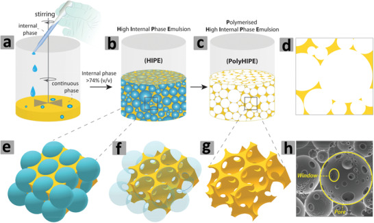
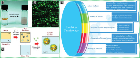
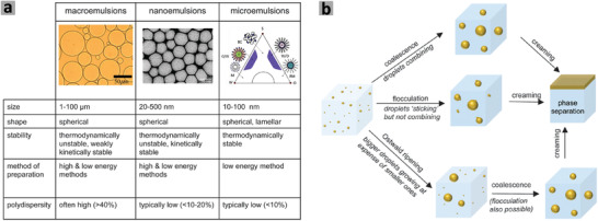
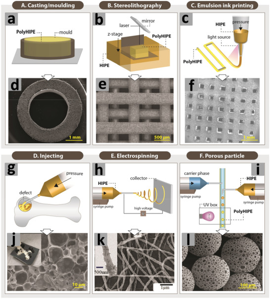
Emulsion templating is at the forefront of producing a wide array of porous materials that offers interconnected porous structure, easy permeability, homogeneous flow-through, high diffusion rates, convective mass transfer, and direct accessibility to interact with atoms/ions/molecules throughout the exterior and interior of the bulk. These interesting features together with easily available ingredients, facile preparation methods, flexible pore-size tuning protocols, controlled surface modification strategies, good physicochemical and dimensional stability, lightweight, convenient processing and subsequent recovery, superior pollutants remediation/monitoring performance, and decent recyclability underscore the benchmark potential of the emulsion-templated porous materials in large-scale practical environmental applications. To this end, many research breakthroughs in emulsion templating technique witnessed by the recent achievements have been widely unfolded and currently being extensively explored to address many of the environmental challenges. Taking into account the burgeoning progress of the emulsion-templated porous materials in the environmental field, this review article provides a conceptual overview of emulsions and emulsion templating technique, sums up the general procedures to design and fabricate many state-of-the-art emulsion-templated porous materials, and presents a critical overview of their marked momentum in adsorption, separation, disinfection, catalysis/degradation, capture, and sensing of the inorganic, organic and biological contaminants in water and air.

Keywords: emulsion templating; environmental remediation; porous materials; sensing; water/air treatment.


Conflict of interest statement

The authors declare no conflict of interest.

Figures

Figure 1
Figure 1
Steps involved in preparation of polymerized high internal phase emulsion (polyHIPE). a,b) The dropwise addition of the dispersed phase into the continuous phase to obtain HIPE, c) polymerization of the HIPE, d) 2D projection of polyHIPE, e–g) the pores and windows formation, and h) Scanning electron microscopy (SEM) image of the polyHIPE. Reproduced under the terms of the Creative Commons Attribution License (CC BY).[ 30 ] Copyright 2020, Aldemir Dikici and Claeyssens, published by Frontiers.
Figure 2
Figure 2
a) A digital photograph shows emulsification of the silicone oil (20%) and water (80%). b) A fluorescence micrograph of the O/W emulsion, scale bar 10 µm. Reproduced under the terms of the Creative Commons CC BY license.[ 33 ] Copyright 2017, The Authors(s), published by Springer Nature. c) Schematic illustration shows the classification of emulsions. d) The scheme shows how a water‐in‐oil‐in‐water (W/O/W) emulsion is prepared. Reproduced with permission.[ 35 ] Copyright 2018, Elsevier.
Figure 3
Figure 3
a) Classification of macroemulsion, nanoemulsion, and microemulsions based on size, shape, stability, preparation method, and polydispersity. b) A schematic representation of emulsion destabilization mechanisms. Reproduced under the terms of the Creative Commons CC BY‐NC 3.0 license.[ 58 ] Copyright 2005, The Author(s), published by Royal Society of Chemistry.
Figure 4
Figure 4
a–c,g–i) Setups of different fabrication routes. d–f),j–l) SEM images of emulsion templated scaffolds. Reproduced under the terms of the Creative Commons Attribution License (CC BY).[ 30 ] Copyright 2020, Aldemir Dikici and Claeyssens, published by Frontiers.
Figure 5
Figure 5
a) Schematic illustration of the preparation of porous polymeric monoliths via gel‐emulsion templating. Reproduced with permission.[ 110 ] Copyright 2019, Wiley‐VCH. b) Schematic representation of preparing hierarchically porous emulsion‐templated syndiotactic polystyrene (sPS) monoliths via crystallization‐induced gelation; c) the sPS monolith exhibits low density, superhydrophobicity, and nanofibrous porous structure. Adapted with permission.[ 112 ] Copyright 2019, American Chemical Society. d) Modification of poly(styrene‐co‐4‐nitrophenylacrylate) [P(St‐co‐NPA)] PolyHIPEs with piperazine. Reproduced with permission.[ 117 ] Copyright 2007, Elsevier.
Figure 6
Figure 6
a–c) Schematic demonstration of the P(St‐co‐DEAEMA) membrane preparation. Reproduced with permission.[ 119 ] Copyright 2017, American Chemical Society. Schematic representation for the preparation of polyampholyte polyHIPEs from oppositely charged monomers AMPTMA and 2‐acrylamido‐2‐methyl‐1‐propanesulfonic acid (AMPS): d) Three ways of mixing the monomers; e) surface groups in the emulsion‐templated pores. Reproduced with permission.[ 147 ] Copyright 2020, Elsevier. f) Schematic illustration for the preparation of superporous pretreated yeast poly(acrylic acid) (PAA) monoliths. Adapted with permission.[ 155 ] Copyright 2019, Elsevier.
Figure 7
Figure 7
a) The scheme shows phase inversion of W/O HIPE used to prepare HIPE W/O/W double emulsions. b) Polymerization of the monomer (oil) phase to generate polyHIPE microspheres. Reproduced with permission.[ 168 ] Copyright 2014, American Chemical Society. c) Preparation of polyHIPE PAM beads by O/W/O sedimentation polymerization: The scheme shows a pre‐formed O/W HIPE that is injected into a glass column containing hot oil. Adapted with permission.[ 23 ] Copyright 2005, Royal Society of Chemistry. d) Uniform PAM beads with diameters around 1.5 mm; e) whole bead (scale bar = 500 µm); f) highly porous surface and internal structure of the sectioned bead. Reproduced with permission.[ 97 ] Copyright 2002, American Chemical Society.
Figure 8
Figure 8
Schematic representation for the preparation of polyHIPE microspheres by a fluidics approach: a) HIPE is injected using b) a syringe pump into a flowing fluid in d) a tubing controlled by c) a peristaltic pump; e) the HIPE drops are polymerized under UV irradiation and subsequently f) collected in a container. Reproduced with permission.[ 161 ] Copyright 2019, Elsevier. g–i) SEM images of the microspheres prepared by the controlled stirred‐tank reactor (CSTR) method; j–l) SEM images of the microspheres fabricated by the microfluidics approach. Reproduced under a Creative Commons Attribution (CC BY) license.[ 78 ] Copyright 2018, The Author(s). Published by AIP Publishing.
Figure 9
Figure 9
Schematic representation of the a) hydroxyl terminated polyHIPE and b) covalently bonded silica−polyHIPE composite networks. Reproduced under a Creative Commons Attribution 4.0.[ 190 ] Copyright 2017, The Authors(s), published by Springer Nature. c) Schematic illustration for the preparation of monolithic magnetic macroporous CS‐PAA hydrogel. d) Digital photograph and optical microscope images of Fe3O4‐stabilized Pickering emulsion at a e) magnification of 100 and a f) magnification of 1000. Adapted with permission.[ 192 ] Copyright 2016, Elsevier.
Figure 10
Figure 10
a) SEM image of Fe3O4 NPs and b) photograph of emulsions in the inset image; c) water contact angle of the PS foam; d) photograph of the PS foam on the water surface; and e) image showing adsorption of diesel by the PS foam. Adapted under a Creative Commons Attribution‐NonCommercial 3.0 Unported Licence.[ 196 ] Copyright 2017, The author(s), published by Royal Society of Chemistry. f) Scheme for the preparation of PAA‐Fe3O4‐PAA composite beads. Reproduced with permission.[ 103 ] Copyright 2019, American Chemical Society. g) Schematic view of the preparation of the PAA‐AO‐PEI (AO = alumina) NC beads. Reproduced with.[ 201 ] Copyright 2021, American Chemical Society.
Figure 11
Figure 11
a) Schematics of the Ag NPs‐decorated emulsion‐templated hierarchically porous PVI beads, where the SEM image shows the pore surface morphology of the PVI beads and the transmission electron microscopy (TEM) image indicates the presence of Ag NPs. Reproduced with permission.[ 102 ] Copyright 2017, American Chemical Society. Preparation of b) Ag‐incorporated melamine‐based microporous organic polymer (m‐MOP) particles and c) Ag‐incorporated m‐MOP particles‐decorated PAM monolith. Reproduced with permission.[ 205 ] Copyright 2020, Elsevier. d) SEM image of Cu3(BTC)2MOF@polyHIPE. Reproduced with permission.[ 208 ] Copyright 2008, Wiley‐VCH. SEM images show e) single bead view (scale bar = 500 µm), f) porous internal structure (scale bar = 200 µm), and g) porous internal structure (scale bar = 50 µm) of silica bead. Adapted with permission.[ 182 ] Copyright 2003, Wiley‐VCH.
Figure 12
Figure 12
a) Schematic illustration for the step‐wise preparation of hierarchically porous GNP–silica composite beads. SEM images of GNP–silica composite beads showing b) porous structure and interconnected emulsion‐templated pores, and c) distribution of GNPs over silica surface. d) SEM image (cross‐sectional view) and e) energy‐dispersive X‐ray map of AO–GNP composite bead, and f) distribution of GNPs over AO surface. Adapted with permission.[ 222 ] Copyright 2006, Royal Society of Chemistry.
Figure 13
Figure 13
a) Schematic illustration for the preparation of ZnO/PDCPD NCs and macroporous ZnO Foams. Reproduced with permission.[ 226 ] Copyright 2014, American Chemical Society. SEM images of b) a single porous gold bead prepared by using GNPs as the building blocks and c) its cross‐sectional and d,e) surface views showing the pore structures. SEM images of f) a single porous gold bead (cross‐sectional view) prepared via in situ reduction of HAuCl4 and g) its internal pores structure. h) Hollow gold bead resulted from the calcination of non‐uniformly distributed gold‐loaded porous polymer bead and i) its internal pores structure. Adapted with permission.[ 228 ] Copyright 2004, Wiley‐VCH.
Figure 14
Figure 14
a,b,d–f) SEM images of LiFePO4 NPs‐coated carbon foam at different magnifications and c) a bare carbon foam. g,h) TEM images confirm the presence of LiFePO4 NPs. i,j) Cartoons show the entrapment of LiFePO4 NPs into the pores of carbon to form a LiFePO4–carbon composite layer. Adapted with permission.[ 237 ] Copyright 2014, Royal Society of Chemistry. k) Reduced graphene oxide (rGO)‐stabilized PDVB polyHIPE monolith (left) and the resulting carbon monolith after carbonization (right), scale bar 5 mm; l) SEM image of PDVB monolith, scale bar 100 µm; m) SEM image of the carbon polyHIPE monolith and the inset image showing rGO platelets, scale bar 100 µm and inset scale bar 400 nm. Adapted under a Creative Commons Attribution 3.0 Unported Licence.[ 241 ] Copyright 2018, The Author(s), published by the Royal Society of Chemistry. n) SEM images showing the HIPE‐templated porous carbon and the mesoporous pore wall (in the inset). Reproduced with permission.[ 233 ] Copyright 2010, American Chemical Society.
Figure 15
Figure 15
a) Image of HTC‐polyHIPE prepared with an oil percentage of 80%; b,c) corresponding SEM images at low and high magnifications show the macroporous structure; d) the image of pyrolyzed HTC‐polyHIPE at 750 °C; e,f) corresponding SEM images at low and high magnifications show the macroporous structure. Adapted with permission.[ 249 ] Copyright 2103, Wiley‐VCH. g) Scheme shows the preparation of nanoporous carbon (NPC) sheets from silica‐PAM polyHIPE. Reproduced with permission.[ 251 ] Copyright 2018, Elsevier. h–k) Porous structure and l) preparation scheme of chemically modified graphene network. h) The emulsion‐templated pore structure, scale bar 10 µm; i) the pore wall, scale bar 2 µm; j) the triple junction between emulsion‐templated pores, scale bar 1 µm; k) the pore wall surface shows the ice‐templated structure, scale bar 2 µm; l) the preparation scheme with the images shows the sample evolution. Reproduced under a Creative Commons Attribution 4.0 International License.[ 259 ] Copyright 2014, Springer Nature.
Figure 16
Figure 16
Graphics show removal of a) Cu2+ and Pb2+ ions by supermacroporous CS‐PAA monolithic hydrogel. Adapted with permission.[ 94 ] Copyright 2016, Elsevier. b) Pb(II) and CV by magnetic hierarchically porous PAA‐Fe3O4 NC bead. Reproduced with permission.[ 103 ] Copyright 2019, American Chemical Society. c) Cr(VI) and CR by PAA‐AO‐PEI bead. Reproduced with permission.[ 201 ] Copyright 2021, American Chemical Society. d) Schematic illustrates the plausible mechanism of arsenate adsorption by hydrated ferric oxides NPs‐embedded porous AMPS‐based polyHIPE monoliths. Reproduced with permission.[ 198 ] Copyright 2019, American Chemical Society. e) Image reveals adsorption of erythrosine dye by (3‐acrylamidopropyl)‐trimethylammonium chloride‐based cationic polyelectrolyte monolith. Reproduced with permission.[ 146 ] Copyright 2018, American Chemical Society.
Figure 17
Figure 17
Images show amidoxime‐modified hollow porous melamine resin polymer microspheres before adsorption (a,c) and after adsorption (b,d) of U(VI). Reproduced with permission.[ 165 ] Copyright 2020, Elsevier. e) Photograph shows dyes removal by macroporous amphoteric polyelectrolyte monolith. Reproduced with permission.[ 147 ] Copyright 2020, Elsevier. f) Water polluted with gasoline and dyed with 1,6,7,12‐tetra‐tert‐butylphenoxyperylene‐3,4,9,10‐tetracarboxylic dianhydride, g) addition of porous PS monolith to gasoline mixture, h) adsorption of gasoline by monolith, i) monolith recovery after adsorption, j) pressing of monolith to remove gasoline, and k) washing of monolith for reuse. Reproduced with permission.[ 109 ] Copyright 2013, Royal Society of Chemistry. The graphs show l) adsorption capacities of LMMG‐based W/O gel emulsion‐templated porous polymeric monolith (M‐3), m) regeneration studies of monoliths prepared via different methods (M‐1–M‐5) using kerosene oil as an example, and n) a digital photograph of M‐3 monolith. M‐1–M‐5 indicates monoliths prepared with different silanes. Adapted with permission.[ 181 ] Copyright 2014, Royal Society of Chemistry.
Figure 18
Figure 18
Photographs demonstrate a) sorption/compression/resorption, b) recovery, and again resorption of the crude oil from oil–water mixture by using emulsion‐templated covalently bonded silica−polymer composites, and c) flexible/compressible nature of the adsorbent. A red dye is added into the crude oil for easy observation. Reproduced under a Creative Commons Attribution 4.0.[ 190 ] Copyright 2017, The Authors(s), published by Springer Nature. Photographs show the removal of d) diesel and e) tetrachloromethane (stained with Sultan VI) from water. Reproduced under a Creative Commons Attribution‐NonCommercial 3.0 Unported Licence.[ 196 ] Copyright, The Author(s), published by the Royal Society of Chemistry. Images of CO2‐controlled O/W separation. Separation of f) water/chloroform (red) using dried membrane and g) water/hexane (yellow) by CO2‐treated membrane. Reproduced with permission.[ 119 ] Copyright 2017, American Chemical Society. h) Schematics illustrates oil absorption from water surface, underwater oil, and emulsified oil by SPS monolith. Reproduced with permission.[ 112 ] Copyright 2019, American Chemical Society.
Figure 19
Figure 19
a) Cartoons illustrate the use of the Ag NP‐decorated emulsion‐templated hierarchically porous PVI beads to treat water contaminated with inorganic, organic, and biological pollutants. Reproduced with permission.[ 102 ] Copyright 2017, American Chemical Society. b) Schematics of the plausible mechanism for photodegradation of organic dyes and microbes by porous TiO2 beads. Reproduced under a Creative Commons Attribution‐NonCommercial 3.0 Unported Licence.[ 101 ] Copyright 2018, The Author(s), published by the Royal Society of Chemistry. c) Reaction between PEI‐based adsorbent and CO2. d) Representative illustration of light‐triggered CO2 breathing. Reproduced with permission.[ 288 ] Copyright 2017, American Chemical Society. e) Photographic demonstration of the compartment with cigarette smoke containing polluted air and the compartment with clear air. The two compartments are connected with a filter packed with amino‐functionalized P(St‐co‐MMA). f) After turning on the fan, the particulate matter is removed after passing the polluted air through the filter, indicated with the red arrow. Reproduced with permission.[ 187 ] Copyright 2018, Elsevier.

References

    1. a) Kuppusamy S., Venkateswarlu K., Megharaj M., Mayilswami S., Lee Y. B., Chemosphere 2017, 186, 607; - PubMed
    2. b) Awasthi A. K., Zeng X., Li J., Environmental pollution 2016, 211, 259; - PubMed
    3. c) Landrigan P. J., Fuller R., Fisher S., Suk W. A., Sly P., Chiles T. C., Bose‐O'Reilly S., Sci. Total Environ. 2019, 650, 2389; - PubMed
    4. d) Santibáñez‐Andrade M., Quezada‐Maldonado E. M., Osornio‐Vargas Á., Sánchez‐Pérez Y., García‐Cuellar C. M., Environmental pollution 2017, 229, 412. - PubMed
    1. a) Khin M. M., Nair A. S., Babu V. J., Murugan R., Ramakrishna S., Energy Environ. Sci. 2012, 5, 8075;
    2. b) Yasri N. G., Gunasekaran S., in Enhancing Cleanup of Environmental Pollutants, Springer, Berlin: 2017, p. 5;
    3. c) Huang D., Hu C., Zeng G., Cheng M., Xu P., Gong X., Wang R., Xue W., Sci. Total Environ. 2017, 574, 1599; - PubMed
    4. d) Dasgupta J., Sikder J., Chakraborty S., Curcio S., Drioli E., J. Environ. Manage. 2015, 147, 55; - PubMed
    5. e) Homaeigohar S., Elbahri M., Materials 2014, 7, 1017; - PMC - PubMed
    6. f) Lu F., Astruc D., Coord. Chem. Rev. 2020, 408, 213180;
    7. g) Maleki H., Chem. Eng. J. 2016, 300, 98;
    8. h) Ye S., Yan M., Tan X., Liang J., Zeng G., Wu H., Song B., Zhou C., Yang Y., Wang H., Appl. Catal., B 2019, 250, 78;
    9. i) Ye S., Zeng G., Tan X., Wu H., Liang J., Song B., Tang N., Zhang P., Yang Y., Chen Q., Appl. Catal., B 2020, 269, 118850.
    1. Samanta P., Desai A. V., Let S., Ghosh S. K., ACS Sustainable Chem. Eng. 2019, 7, 7456.
    1. Yang X.‐Y., Chen L.‐H., Li Y., Rooke J. C., Sanchez C., Su B.‐L., Chem. Soc. Rev. 2017, 46, 481. - PubMed
    1. Okesola B. O., Smith D. K., Chem. Soc. Rev. 2016, 45, 4226. - PubMed

Publication types

LinkOut - more resources