

Vivaldi Antenna Arrays Feed by Frequency-Independent Phase Shifter for High Directivity and Gain Used in Microwave Sensing and Communication Applications
- PMID: 34577298
- PMCID: PMC8472483
- DOI: 10.3390/s21186091
Vivaldi Antenna Arrays Feed by Frequency-Independent Phase Shifter for High Directivity and Gain Used in Microwave Sensing and Communication Applications
Abstract
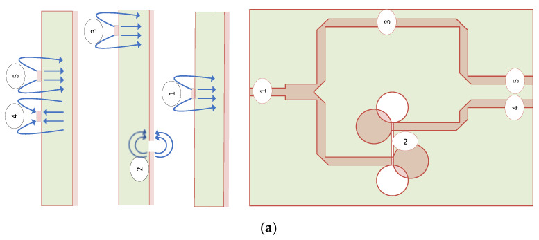
This paper describes a novel feed system for compact, wideband, high gain six-slot Vivaldi antenna arrays on a single substrate layer using a unique combination of power splitters based on binary T-junction power splitter topology, frequency-independent phase shifter, and a T-branch. The proposed antenna system consists of six Vivaldi antennas, three on the left, and three on the right arm. Each arm connects with T-junction power divider splitter topology, given that the right arm is linked through a frequency-independent phase shifter. Phase shifters ensure that the beam is symmetrical without splitting in a radiating plane so that highly directive radiation patterns occur. The optimal return losses (S-parameters) are well enriched by reforming Vivaldi's feeding arms and optimizing Vivaldi slots and feeds. A novel feature of our design is that the antenna exhibits the arrangements of a T-junction power splitter with an out-of-phase feeding mechanism in one of the arms, followed by a T-branching feeding to even arrays of proper Vivaldi antenna arrangement contributing high realized gain and front-to-back ratio up to 14.12 dBi and 23.23 dB respectively applicable for not only ultra-wideband (UWB) application, also for sensing and position detecting. The high directivity over the entire UWB frequency band in both higher and lower frequency ranges ensures that the antenna can be used in microwave through-wall imaging along with resolution imaging for ground penetration radar (GPR) applications. The fabricated antenna parameters are in close agreement with the simulated and measured results and are deployed for the detection of targets inside the voids of the concrete brick.
Keywords: Vivaldi antenna array; ground penetration radar; power dividers; ultra-wideband antenna.
Conflict of interest statement
The authors declare no conflict of interest.
Figures


Similar articles
-
Ultra-Wide Band Double-Slot Podal and Antipodal Vivaldi Antennas Feed by Compact Out-Of-Phase Power Divider Slot for Fluid Properties Determination.Sensors (Basel). 2022 Jun 16;22(12):4543. doi: 10.3390/s22124543. Sensors (Basel). 2022. PMID: 35746326 Free PMC article.
-
1-Tx/5-Rx Through-Wall UWB Switched-Antenna-Array Radar for Detecting Stationary Humans.Sensors (Basel). 2020 Nov 29;20(23):6828. doi: 10.3390/s20236828. Sensors (Basel). 2020. PMID: 33260403 Free PMC article.
-
A Compact Dual-Polarized Vivaldi Antenna with High Gain for Tree Radar Applications.Sensors (Basel). 2024 Jun 27;24(13):4170. doi: 10.3390/s24134170. Sensors (Basel). 2024. PMID: 39000948 Free PMC article.
-
Overview of Vivaldi Antenna Selection for Through-Wall Radar Applications.Sensors (Basel). 2024 Oct 10;24(20):6536. doi: 10.3390/s24206536. Sensors (Basel). 2024. PMID: 39460018 Free PMC article. Review.
-
Ultra-Wideband Antennas for Biomedical Imaging Applications: A Survey.Sensors (Basel). 2022 Apr 22;22(9):3230. doi: 10.3390/s22093230. Sensors (Basel). 2022. PMID: 35590917 Free PMC article. Review.
Cited by
-
Design of Wideband High-Gain Patch Antenna Array for High-Temperature Applications.Sensors (Basel). 2023 Apr 8;23(8):3821. doi: 10.3390/s23083821. Sensors (Basel). 2023. PMID: 37112162 Free PMC article.
-
Localization of Dielectric Anomalies with Multi-Monostatic S11 Using 2D MUSIC Algorithm with Spatial Smoothing.Sensors (Basel). 2022 Jul 15;22(14):5293. doi: 10.3390/s22145293. Sensors (Basel). 2022. PMID: 35890973 Free PMC article.
-
Generalized Concept and MATLAB Code for Modeling and Analyzing Wideband 90° Stub-Loaded Phase Shifters with Simulation and Experimental Verifications.Sensors (Basel). 2023 Sep 9;23(18):7773. doi: 10.3390/s23187773. Sensors (Basel). 2023. PMID: 37765830 Free PMC article.
-
Design of a Novel Wideband Leaf-Shaped Printed Dipole Array Antenna Using a Parasitic Loop for High-Power Jamming Applications.Sensors (Basel). 2021 Oct 17;21(20):6882. doi: 10.3390/s21206882. Sensors (Basel). 2021. PMID: 34696100 Free PMC article.
-
Ultra-Wide Band Double-Slot Podal and Antipodal Vivaldi Antennas Feed by Compact Out-Of-Phase Power Divider Slot for Fluid Properties Determination.Sensors (Basel). 2022 Jun 16;22(12):4543. doi: 10.3390/s22124543. Sensors (Basel). 2022. PMID: 35746326 Free PMC article.
References
-
- He S.H., Shan W., Fan C., Mo Z.C., Yang F.H., Chen J.H. An improved vivaldi antenna for vehicular wireless communication systems. IEEE Antennas Wirel. Propag. Lett. 2014;13:1505–1508. doi: 10.1109/LAWP.2014.2343215. - DOI
-
- Reid E.W., Ortiz-Balbuena L., Ghadiri A., Moez K. A 324-element vivaldi antenna array for radio astronomy instrumentation. IEEE Trans. Instrum. Meas. 2012;61:241–250. doi: 10.1109/TIM.2011.2159414. - DOI
-
- Abbak M., Akinci M.N., Çayören M., Akduman I. Experimental microwave imaging with a novel corrugated vivaldi antenna. IEEE Trans. Antennas Propag. 2017;65:3302–3307. doi: 10.1109/TAP.2017.2670228. - DOI
-
- Pozar D.M. Microstrip antennas. Proc. IEEE. 1992;80:79–91. doi: 10.1109/5.119568. - DOI
-
- Kumar P., Urooj S. A miniaturized low-profile UWB antenna for microwave imaging applications; Proceedings of the International Conference on Power Electronics, Control and Automation (ICPECA); New Delhi, India. 16–17 November 2019; - DOI
MeSH terms
Grants and funding
LinkOut - more resources
Full Text Sources
Miscellaneous
