Review
. 2022 Jan;47(1):20-40.
doi: 10.1038/s41386-021-01156-6. Epub 2021 Sep 28.

Prefrontal connectomics: from anatomy to human imaging

Affiliations
Review

Prefrontal connectomics: from anatomy to human imaging

Suzanne N Haber et al. Neuropsychopharmacology. 2022 Jan.

Abstract

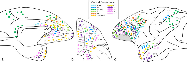
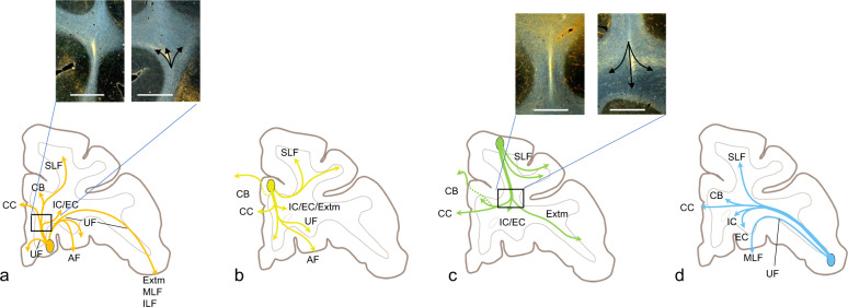
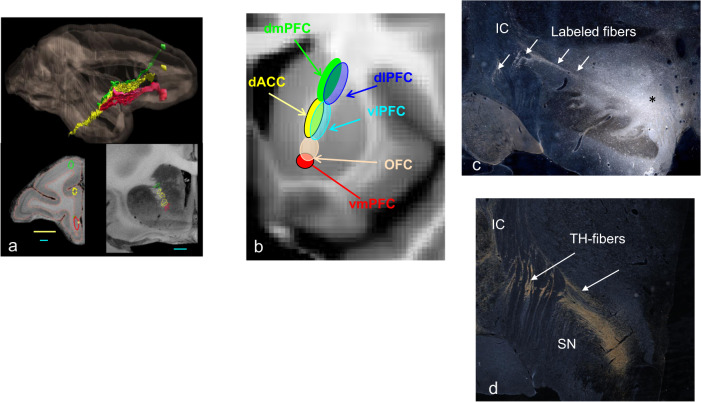
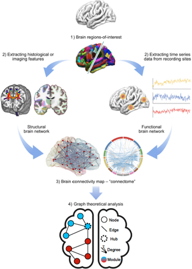
The fundamental importance of prefrontal cortical connectivity to information processing and, therefore, disorders of cognition, emotion, and behavior has been recognized for decades. Anatomic tracing studies in animals have formed the basis for delineating the direct monosynaptic connectivity, from cells of origin, through axon trajectories, to synaptic terminals. Advances in neuroimaging combined with network science have taken the lead in developing complex wiring diagrams or connectomes of the human brain. A key question is how well these magnetic resonance imaging (MRI)-derived networks and hubs reflect the anatomic "hard wiring" first proposed to underlie the distribution of information for large-scale network interactions. In this review, we address this challenge by focusing on what is known about monosynaptic prefrontal cortical connections in non-human primates and how this compares to MRI-derived measurements of network organization in humans. First, we outline the anatomic cortical connections and pathways for each prefrontal cortex (PFC) region. We then review the available MRI-based techniques for indirectly measuring structural and functional connectivity, and introduce graph theoretical methods for analysis of hubs, modules, and topologically integrative features of the connectome. Finally, we bring these two approaches together, using specific examples, to demonstrate how monosynaptic connections, demonstrated by tract-tracing studies, can directly inform understanding of the composition of PFC nodes and hubs, and the edges or pathways that connect PFC to cortical and subcortical areas.


Conflict of interest statement

EB is a National Institute of Health Research Senior Investigator and serves on the scientific advisory board of Sosei Heptares and as a consultant for GlaxoSmithKline. The remaining authors declare no competing interests.

Figures

Fig. 1
Fig. 1. A general overview of the denser connections to prefrontal areas.
a Sagittal view, b orbital view, and c lateral view. For a more complete connectional description for each area, see the references listed in section “Frontocortical connectivity and pathways” of the review. Each dot represents connections from the corresponding cortical area indicated by its color. Blue indicates inputs from vlPFC (light blue = areas 45 and 44, dark blue = area 47); green indicates inputs form dlPFC (light green = area 9; dark green = areas 46 and 9/46); red/orange indicates inputs from ACC (red = area 24, orange = area 32, unfilled dots = area 25; purple/pink indicates inputs from OFC (dark purple = area 11, dark pink = area 14, light pink = area 14); pale pink indicates frontal pole (area 10). amts anterior middle temporal sulcus, CC corpus callosum, cgs cingulate sulcus, cs central sulcus, dACC dorsal anterior cingulate cortex, ios inferior occipital sulcus, ips intraparietal sulcus, lf lateral fissure, lorb lateral orbital sulcus, morb medial orbital sulcus, olfs olfactory sulcus, OPAI orbital periallocortex, Opro orbital proisocortex, ots occipitotemporal sulcus, ProM area ProM (promotor), rACC rostral anterior cingulate cortex, rhf rhinal fissure, ros rostral sulcus, sACC subgenual anterior cingulate cortex, spd superior postcentral dimple, sts superior temporal sulcus.
Fig. 2
Fig. 2. Schematic demonstrating axons entering the white matter from ventral, medial, dorsal, and lateral PFC regions and branching to enter different pathways.
a Fibers exiting the OFC. Box indicates the inset of photomicrographs of the stalk and branching axons. b Fibers exiting the anterior cingulate cortex. c Fibers exiting the dorsolateral PFC. Box indicates the inset of photomicrographs of stalk and branching axons. d Fibers exiting the ventrolateral prefrontal cortex. AF amygdalofugal pathway, CB cingulum bundle, CC corpus callosum, EC external capsule, Extm extreme capsule, IC internal capsule, IL inferior longitudinal fasciculus, MLF medial longitudinal fasciculus, SLF superior longitudinal fasciculus, UF uncinate fasciculus.
Fig. 3
Fig. 3. Pathways through the anterior limb of the internal capsule (a, b) and medial forebrain bundle (c, d).
a Sagittal and coronal views of the dorsoventral positions of fibers from the medial wall (green = area 9m; yellow = area 24; red = area 14m) traveling through the ALIC; lower left image represents each injection site placement. b Segmentation of the ALIC. Coronal view: red = vmPFC; pink = OFC; yellow = dACC; teal = vlPFC; green = dmPFC; blue = dlPFC. c Tritiated amino acid injection into the ventral tegmental area with labeled fibers streaming laterally, crossing through the internal capsule. d Tyrosine hydroxylase-positive staining, illustrating the trajectory of dopamine axon similar to the (c). IC internal capsule, SN substantia nigra.
Fig. 4
Fig. 4. Human brain network analysis: high-level schematic.
Brain regions or nodes are defined based on anatomical, functional, or multimodal parcellations, thus subdividing the whole brain into p regional nodes (1). Connectivity between nodes can be estimated in many different ways, to define the weight of an edge or connection between each possible pair of nodes. Anatomical connectivity (2, left) can be estimated by dMRI tractography, structural covariance, or morphometric similarity; functional connectivity (2, right) can be estimated by the correlation between nodal mean time series. The resulting (p × p) matrix is the connectome, which can be represented in diverse formats, including (left) an anatomical rendering, where the nodes are located at the centroid of each region and a line is drawn between nodes if their pairwise connectivity exceeds an arbitrary threshold; or (right) a ring diagram, where the regional nodes are arranged around the perimeter of the circle (color-coded according to anatomical criteria or modular affiliation) and edges traverse the interior of the circle denoting suprathreshold connectivity. Finally, the complex topological properties of these networks, including hubs and modules, can be estimated using tools from graph theory, here illustrated for the simplest class of binary undirected graphs (from [236]).
Fig. 5
Fig. 5. Functional connectivity profiles of human prefrontal cortical seed regions.
Eight seed regions of lateral and medial PFC (shown in the central panel) were used to estimate the functional connectivity—or fMRI time-series correlations—between the seed and a range of other cortical regions. The eight radar plots show the strength of connectivity between each of the seeds (located at the center of the circles) and 22 other regions (labeled on the perimeter of each circle). The red line shows the strength of functional connectivity in the range −0.4 to 0.5, against the background of three concentric circles representing connectivity of −0.1 (the inner circle), +0.2 (the middle circle), or +0.5 (the outer circle or perimeter) (from [20]).
Fig. 6
Fig. 6. Tractography through the anterior limb of the medial forebrain bundle and ALIC.
ac Pathways through the MFB. a Asterisk indicates tracer injection site; b, c red dot indicates seed placement at the same site as the injection in monkey and human dMRI. Similar to the anatomic tracing, streamlines cross the internal capsule (IC) to the striatum. However, unlike the anatomic tracing experiment, streamlines also enter the IC and continue to travel rostrally, through the IC in both the monkey and human. dg Pathways through the ALIC. a Histology showing fiber pathways following an injection site in the dorsal PFC. b NHP dMRI streamlines generated from a seed at the injection site location. Correct streamlines are indicated with yellow arrows, incorrect streamlines with blue arrows. c Human dMRI data illustrating streamlines following placement of a seed in a similar area of the dorsal PFC. Based on the NHP data, yellow arrows show the likely correct streamlines and blue arrows show the likely incorrect ones. d Organization of cortical fibers in the human ALIC. Red = vmPFC, yellow = ACC, teal = vlPFC, green = dmPFC, blue = dlPFC.
Fig. 7
Fig. 7. The rACC hub.
a Schematic illustration of the FC regions with strong projections in each case. The dashed contour at the center of each schematic represents the rACC and the circles indicate the injection placement for each case. a.1 = injection 1, a.2 = injection 4, a.3 = injection 6. Colored branches represent the strength of inputs (based on cell counts) from each brain region (green = 50%; red = 75%). Case 4 (a.2) showed the most diverse input. b Top: sagittal section showing the localized hub in seven individual monkeys using dMRI tractography. Each red dot marks the center of the hub region in one monkey. The center of the hub was defined by the voxel with the highest weighted sum of probabilistic streamlines from all 29 seeded areas. Bottom: sagittal sections showing the localized hub across human individuals using dMRI tractography. Each red dot marks the center of the hub region in one subject. The center of the hub was defined by the voxel with the highest weighted − sum of probabilistic streamlines from all seeded FC areas. c rs-fMRI connectivity following seed placement in the rACC in similar locations as the anatomic injection sites. Top: seed placements. c.1. Seed placement in the ventral rACC. This placement showed the most limited connections, consistent with the NHP anatomy data. c.2. Seed placement in the central rACC. This placement showed the most diverse connections, consistent with the NHP anatomy data c.3. Seed placement in the dorsal rACC. This placement showed an intermediate level of connections, consistent with the NHP anatomy data.

Similar articles

Cited by

References

    1. Brodmann K. Vergleichende Lokalisationslehre der Grosshirnrinde in ihren Prinzipien dargestellt auf Grund des Zellenbaues. Leipzig: Barth; 1909. p. x, 324.
    1. Vogt O, Vogt C. Ergebnisse unserer Hirnforschung. J Psychol Neurol. 1919;25:277–462.
    1. Nieuwenhuys R. The myeloarchitectonic studies on the human cerebral cortex of the Vogt-Vogt school, and their significance for the interpretation of functional neuroimaging data. Brain Struct Funct. 2013;218:303–52. doi: 10.1007/s00429-012-0460-z. - DOI - PubMed
    1. Zola-Morgan S. Localization of brain function: the legacy of Franz Joseph Gall (1758-1828) Annu Rev Neurosci. 1995;18:359–83. doi: 10.1146/annurev.ne.18.030195.002043. - DOI - PubMed
    1. Catani M, Ffytche DH. The rises and falls of disconnection syndromes. Brain. 2005;128:2224–39. - PubMed

Publication types