Review
. 2021 Nov 15;50(22):12450-12550.
doi: 10.1039/d0cs01336f.

Dye-sensitized solar cells strike back

Affiliations
Review

Dye-sensitized solar cells strike back

Ana Belén Muñoz-García et al. Chem Soc Rev. .

Abstract

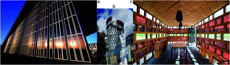
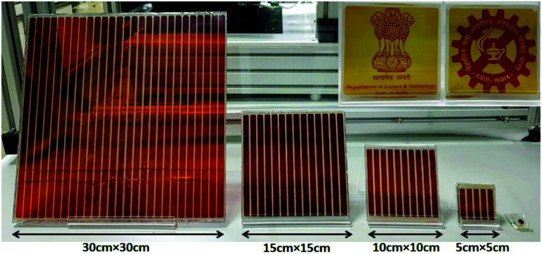
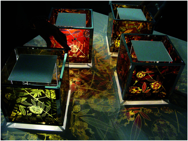
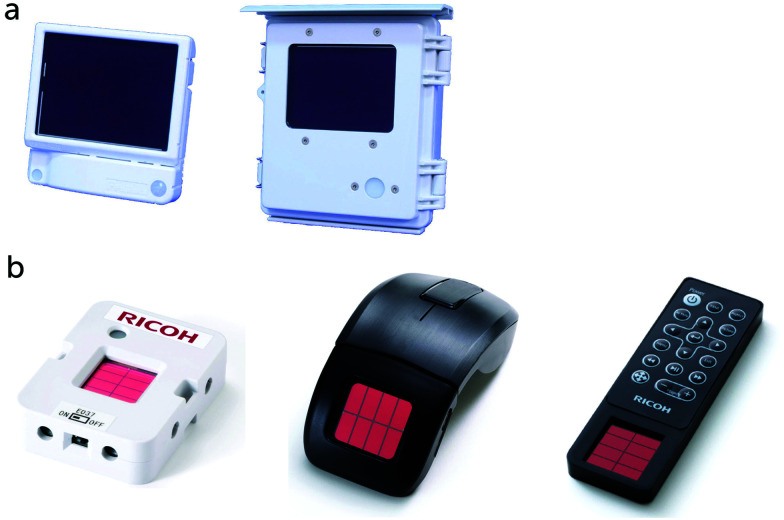
Dye-sensitized solar cells (DSCs) are celebrating their 30th birthday and they are attracting a wealth of research efforts aimed at unleashing their full potential. In recent years, DSCs and dye-sensitized photoelectrochemical cells (DSPECs) have experienced a renaissance as the best technology for several niche applications that take advantage of DSCs' unique combination of properties: at low cost, they are composed of non-toxic materials, are colorful, transparent, and very efficient in low light conditions. This review summarizes the advancements in the field over the last decade, encompassing all aspects of the DSC technology: theoretical studies, characterization techniques, materials, applications as solar cells and as drivers for the synthesis of solar fuels, and commercialization efforts from various companies.


Conflict of interest statement

GB, HP and AH are co-founders and co-owners of Dyenamo AB.

Figures

Fig. 1
Fig. 1. Solar irradiance spectrum. Artwork created by Nick84 and released under Creative Commons BY-SA 3.0 license, ref. .
Fig. 2
Fig. 2. Normalized emission spectra of warm white fluorescent and LED bulbs, and of the AM1.5G standard. Reproduced from ref. with permission from The Royal Society of Chemistry, copyright 2021.
Fig. 3
Fig. 3. Basic diagram of the dye-sensitized solar cell, displaying working mechanism and energy levels.
Fig. 4
Fig. 4. Device structures for dye-sensitized solar cells: (a) sandwich cell, (b) monolithic cell with carbon counter electrode, (c) solid-state DSC (monolithic), and (d) conducting glass-free DSC design.
Fig. 5
Fig. 5. Simulated J–V curves of a solar cell using the Shockley diode model with (red line) and without (blue stripes) series and parallel resistance losses. Rs and Rp are 5 and 1000 Ω cm2, respectively; Js = 1.5 nA cm−2; n = 2. The resistance losses reduce the PCE from 13.1% to 11.2%, due of the reduced fill factor (from 78% to 66%). The black dotted line the is the device's power output with resistance losses. The yellow square represents the device's power output.
Fig. 6
Fig. 6. Representation of a solar cell as a schematic circuit.
Fig. 7
Fig. 7. (a) Impedance spectrum (Nyquist plot) of a dye-sensitized solar cell under illumination, recorded at VOC. (b) Schematic model to fit the EIS under these conditions. Adapted from ref. with permission from the PCCP Owner Societies, copyright 2011.
Fig. 8
Fig. 8. Photocurrent transients of a DSC with a Cu complex-based electrolyte. (a) Under high light intensities and with a relatively thick electrolyte layer (Surlyn: 30 μm) a clear spike is found in the photocurrent onset transient. (b) After switching the light off, a reversal of current can be found in the photocurrent decay transient, due to accumulation of oxidized redox species in the mesoporous electrode, which are reduced by electrons in the TiO2. Adapted from ref. with permission from the PCCP Owner Societies, copyright 2017.
Fig. 9
Fig. 9. (a) Electron lifetime and (b) accumulated charge as a function of VOC for DSCs with a cobalt-based electrolyte, sensitized with D35, Dyenamo blue (DB), or both. Band-edge shifts of the different dyes are small, however a large difference in electron lifetime is found. Adapted with permission from ref. . Copyright 2016 American Chemical Society.
Fig. 10
Fig. 10. The energetic overlap of the initially-formed Frack-Condon state (1MLCT) and the photoluminescence 3MLCT with the acceptor states in anatase TiO2 at pH 1. Intersystem crossing (isc) and internal conversion (ic) compete kinetically with excited-state injection. Inset shows the structure of a Ru(ii) sensitizer undergoing excited-state injection. Adapted with permission from ref. . Copyright 2016 American Chemical Society.
Fig. 11
Fig. 11. (a) Chemical structure of the N-heterocyclic Fe(ii) carbene complex anchored to TiO2. (b) Transient absorption and terahertz kinetic data for the iron carbene complex and for N3. (c) A Jablonski-type diagram. Reprinted with permission from ref. . Copyright 2016 American Chemical Society.
Fig. 12
Fig. 12. (A) Molecular structures of the Dye-X series. (B and C) DFT models of the singly oxidized forms of Dye-X showing (B) the β-LUSO and (C) the existence of σ-holes on the poles of the terminal halogen substituents for the series, with the exception of Dye-F. (D) Scheme of energy levels and electron transfer processes. Adapted with permission from ref. . Copyright 2016 American Chemical Society.
Fig. 13
Fig. 13. Molecular structures of (a) D5, (b) D45 and (c) D35 dyes, and (d) [Cu(tmby)2]2+/+, (e) [Cu(eto)2]2+/+, (f) [Cu(dmp)2]2+/+ and (g) [Cu(dmby)2]2+/+ complexes. Reprinted with permission from ref. . Copyright 2018 American Chemical Society.
Fig. 14
Fig. 14. (a) Transient absorption and (b) transient absorption anisotropy spectroscopy on MP13 sensitized TiO2 films on glass immersed in different environments. The films were pumped with pulsed laser excitation at 430 nm while the oxidized dye signal was probed at 770 nm. The solid lines in (b) are obtained by calculating a moving average of the raw data (also displayed in background). Adapted with permission from ref. . Copyright 2016 American Chemical Society.
Fig. 15
Fig. 15. Examples of recent computational studies on DSC components. (a) electron (green) and hole (blue) densities at the beginning of the simulation (t = 0 fs) and upon electron injection (t = 100 fs) for benzohydroxamic acid anchored on TiO2 with full explicit water solvation. Adapted with permission from ref. . Copyright 2020 American Chemical Society. (b) Analysis of charge transfer parameters in Cu-based electrolytes. Adapted with permission from ref. . Copyright 2018 American Chemical Society. (c) Isosurfaces of band-decomposed charge density of the lowest unoccupied band of the push–pull dye T1/NiO system. Adapted with permission from ref. . Copyright 2019 American Chemical Society. (d) Anchoring geometry of C343 as a model dye on NiO during the molecular dynamics simulation in explicit water. Adapted with permission from ref. . Copyright 2017 American Chemical Society.
Fig. 16
Fig. 16. SEM image of a mesoporous TiO2 film made with the GreatCell Solar 18NR-T paste.
Fig. 17
Fig. 17. SEM micrographs of mesoporous TiO2 microbeads. (a) Adapted with permission from ref. . Copyright 2010 American Chemical Society. (b) Adapted from ref. with permission from The Royal Society of Chemistry, copyright 2014.
Fig. 18
Fig. 18. (a) Inverse opal SnO2 electrode; (b) after coating with a 170 nm shell of TiO2. Adapted from ref. with permission from The Royal Society of Chemistry, copyright 2016.
Fig. 19
Fig. 19. Examples of metal complex-based sensitizers.
Fig. 20
Fig. 20. Contemporary rapid routes to complex organic dyes where X is a halide, M is a transmetallating reagent, and Y is a masked functionality such as a TMS group prior to halide conversion.
Fig. 21
Fig. 21. Examples of high-performing organic charge transfer dyes used in DSC devices.
Fig. 22
Fig. 22. Examples of high-performing organic charge transfer dyes used in DSC devices with “umbrella” type donors.
Fig. 23
Fig. 23. Examples of high voltage dye-designs.
Fig. 24
Fig. 24. Select porphyrin examples discussed in this review.
Fig. 25
Fig. 25. Examples of squaraine-based dyes.
Fig. 26
Fig. 26. Photoresponsive NPI in a non-visible light absorbing state (left) and a visible light absorbing state (right).
Fig. 27
Fig. 27. Chemical structures of cobalt coordination complexes-based redox mediators implemented in DSCs.
Fig. 28
Fig. 28. Chemical structures of copper coordination complexes-based redox mediators implemented in DSCs.
Fig. 29
Fig. 29. Chemical structures of iron coordination complexes-based redox mediators implemented in DSCs.
Fig. 30
Fig. 30. Starting with commercially available o-carborane, a five-step, high-yield synthetic strategy is used to create bis(dicarbollide) species from B(9)-functionalized derivatives of the parent carborane. Reprinted with permission from ref. . Copyright 2010 WILEY-VCH Verlag GmbH & Co. KGaA, Weinheim.
Fig. 31
Fig. 31. Chemical structures of manganese coordination complexes-based redox mediators implemented in DSCs.
Fig. 32
Fig. 32. Chemical structures of vanadium coordination complexes-based redox mediators implemented in DSCs.
Fig. 33
Fig. 33. Chemical structures of small organic molecules-based redox mediators implemented in DSCs.
Fig. 34
Fig. 34. Examples of cations and anions used in ionic liquids.
Fig. 35
Fig. 35. Chemical structures of polymer electrolytes used in DSCs.
Fig. 36
Fig. 36. Examples of carbazole-based organic hole conductors.
Fig. 37
Fig. 37. Examples of triphenylamine-based organic hole conductors.
Fig. 38
Fig. 38. Examples of polymeric hole conductors.
Fig. 39
Fig. 39. Examples of dopants for hole transporting materials.
Fig. 40
Fig. 40. Structures of various carbon allotropes. Reprinted with permission from ref. . Copyright 2013 Mineralogical Society of America.
Fig. 41
Fig. 41. Repeating units of polymers used as counter electrode materials in DSCs.
Fig. 42
Fig. 42. Schematic representation of the charge transfer processes occurring within a NiO-based p-DSC. Recombination processes shown in red. Processes 1–6 defined in the text. Adapted from ref. with permission from The Royal Society of Chemistry, copyright 2019.
Fig. 43
Fig. 43. Examples of metal complex-based sensitizers for p-type DSCs.
Fig. 44
Fig. 44. Examples of triphenylamine-based sensitizers for p-type DSCs.
Fig. 45
Fig. 45. Examples of perylene monoimide- and naphthalene diimide-based sensitizers for p-type DSCs.
Fig. 46
Fig. 46. Examples of different sensitizers for p-type DSCs.
Fig. 47
Fig. 47. Structures of different redox mediators applied in p-DSCs.
Fig. 48
Fig. 48. Schematic diagram of a DSPEC for light-driven water splitting with an assembly-derived TiO2 photoanode for water oxidation to O2 and a dark Pt cathode for proton/water reduction to H2. Reprinted with permission from ref. . Copyright 2015 American Chemical Society.
Fig. 49
Fig. 49. Self-assembled bilayer of a chromophore-catalyst assembly on a metal oxide. Reprinted with permission from ref. . Copyright 2019 American Chemical Society.
Fig. 50
Fig. 50. Photocathode for hydrogen generation. Reprinted with permission from ref. . Copyright 2016 American Chemical Society.
Fig. 51
Fig. 51. Structures of Ru-based water oxidation catalysts.
Fig. 52
Fig. 52. Schematic diagram for a DSPEC for light-driven CO2 splitting into CO and O2 with an assembly-derivatized TiO2 photoanode for water oxidation to O2 and an assembly-derivatized photocathode for CO2 reduction to CO. Reprinted with permission from ref. . Copyright 2015 American Chemical Society.
Fig. 53
Fig. 53. Schematic diagram of a DSPEC wired in series with a DSC. Reprinted with permission from ref. . Copyright 2016 American Chemical Society.
Fig. 54
Fig. 54. (a) The DSC installation at the Conference centre in Lausanne, Switerland, consisting of 1400 W-connected modules of the size 35 × 50 cm2 (in total approx. 150 m2), manufactured by Solaronix in Switzerland. Reproduced with permission from Solaronix S.A., copyright 2021. (b) The DSC installation at the Science Tower in Graz, Austria, consisting of 896 W-connected red DSC devices of 0.6 m2 area each (in total approx. 500 m2), manufactured by H.Glass in Switzerland. Reproduced with permission from H.Glass S.A., copyright 2021. (c) The DSC installation at the Solar Pavillon at Roskilde University in Denmark, consisting of 196 W-connected red DSC panels of area 900 cm2 each (in total approx. 180 m2) made by Dongjin Semichem in South Korea. Architect Jane Ostermann-Petersen. Reproduced with permission from Karina Tengberg, copyright 2021.
Fig. 55
Fig. 55. Indian semi-transparent DSC prototypes from Elixir Technologies and CSIR-National Institute for Interdisciplinary Science & Technology (NIIST). Reproduced with permission from the Indian Ministry of Science and Technology, copyright 2021.
Fig. 56
Fig. 56. An example of artistic DSC devices from Sony displayed at the 10th Eco-Products Conference in Tokyo in 2008. Reproduced with permission from Satoshi Uchida, copyright 2021.
Fig. 57
Fig. 57. (a) DSC-containing sensor systems from Fujikura in Japan for indoor (left) and outdoor (right) applications, respectively. Reproduced with permission from Fujikura Ltd, copyright 2021. (b) Examples of products from Ricoh containing their solid-state DSC devices: environmental sensors for measuring temperature, humidity, illumination, atmospheric pressure, etc., wireless mouse and remote controls for projectors. Reproduced with permission from Ricoh Company Ltd, copyright 2021.
Fig. 58
Fig. 58. Various prototypes including non-visible DSC devices from Exeger in Sweden. Reproduced with permission from Exeger A.B., copyright 2021.
None
Ana Belen Muñoz García (top left), Iacopo Benesperi (4th column, middle), Gerrit Boschloo (4th column, top), Javier J. Concepcion (2nd column, top), Jared Delcamp (3rd column, top), Libby Gibson (3rd column, bottom), Gerald (Jerry) J. Meyer (bottom left), Michele Pavone (2nd column, bottom), Henrik Pettersson (4th column, bottom), Anders Hagfeldt (top right) and Marina Freitag (bottom right)

References

    1. Ritchie H., Energy Mix, https://ourworldindata.org/energy-mix
    1. Archer D., Global Warming: Understanding the Forecast, John Wiley & Sons, 2nd edn, 2012
    1. Ritchie H. and Roser M., Renewable Energy, https://ourworldindata.org/renewable-energy
    1. IEA, Renewables 2020, International Energy Agency, 202010.1787/c74616c1-en - DOI
    1. O'Regan B. Grätzel M. Nature. 1991;353:737–740. doi: 10.1038/353737a0. - DOI