

Decoding four hand gestures with a single bipolar pair of electrocorticography electrodes
- PMID: 34607318
- PMCID: PMC8744490
- DOI: 10.1088/1741-2552/ac2c9f
Decoding four hand gestures with a single bipolar pair of electrocorticography electrodes
Abstract
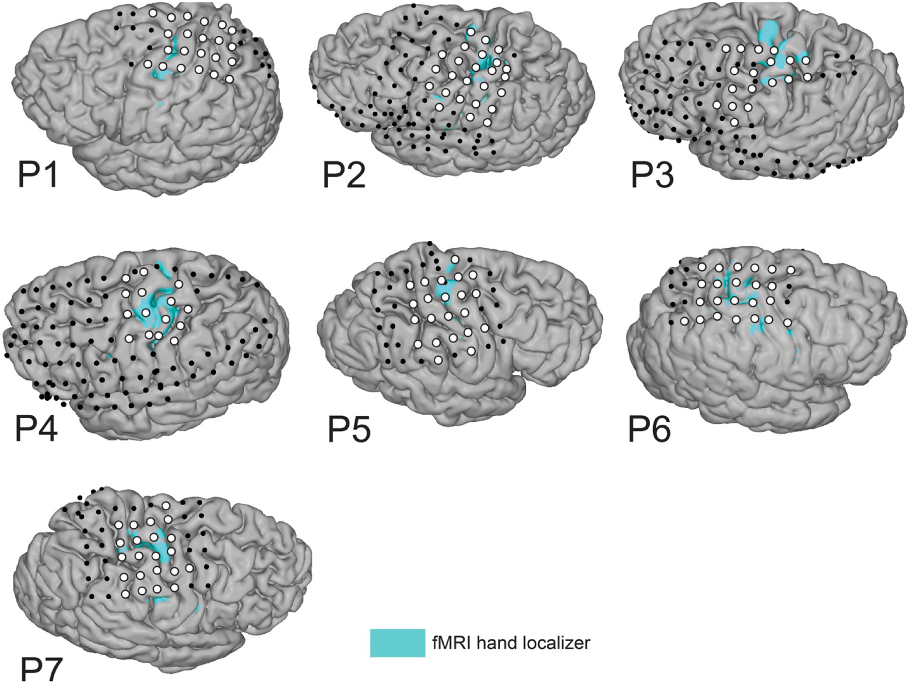
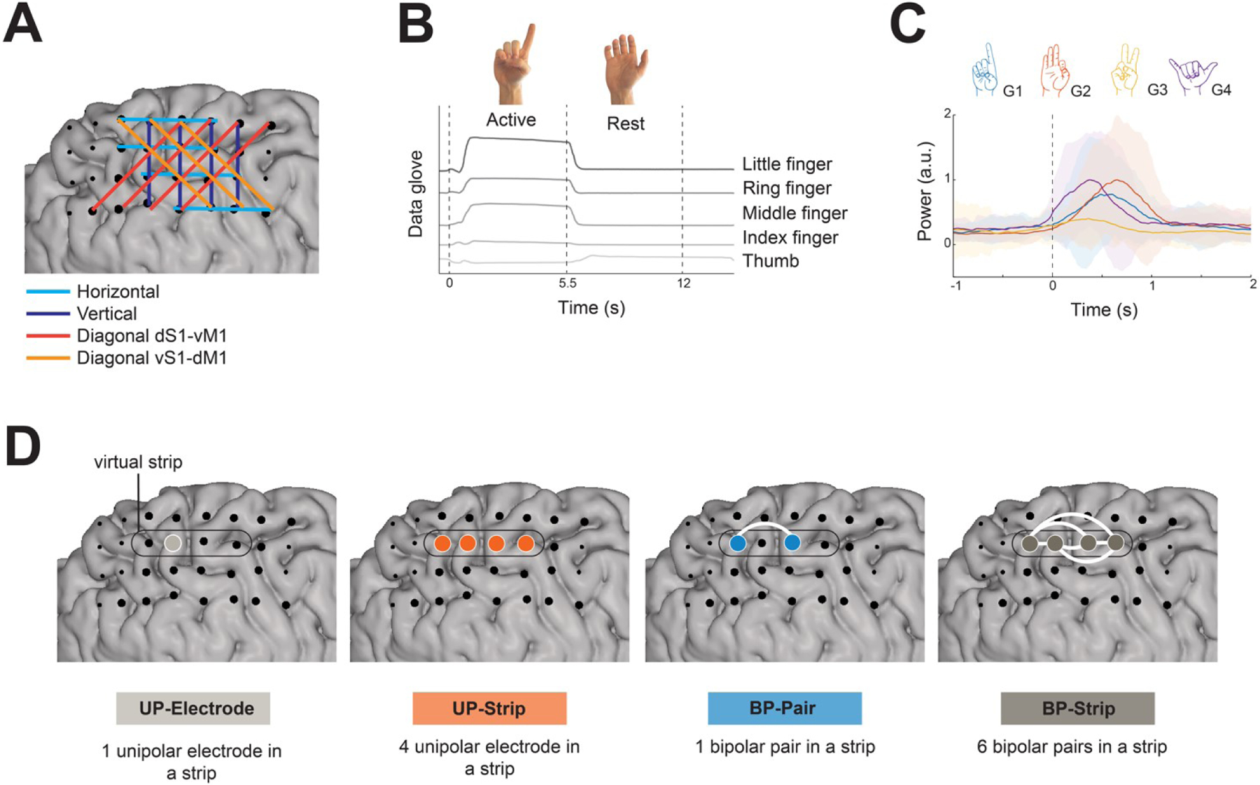
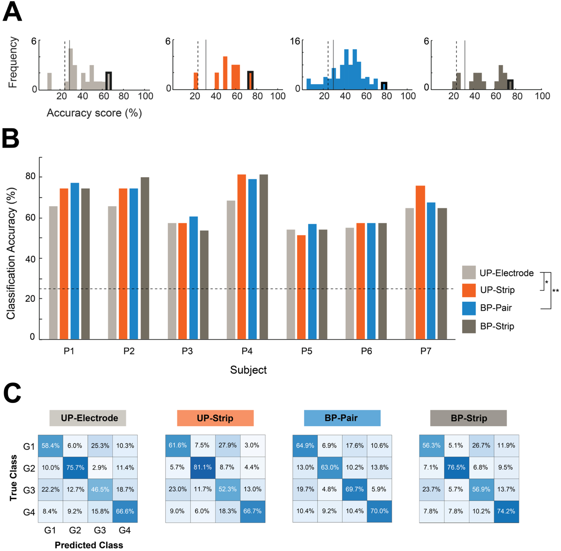
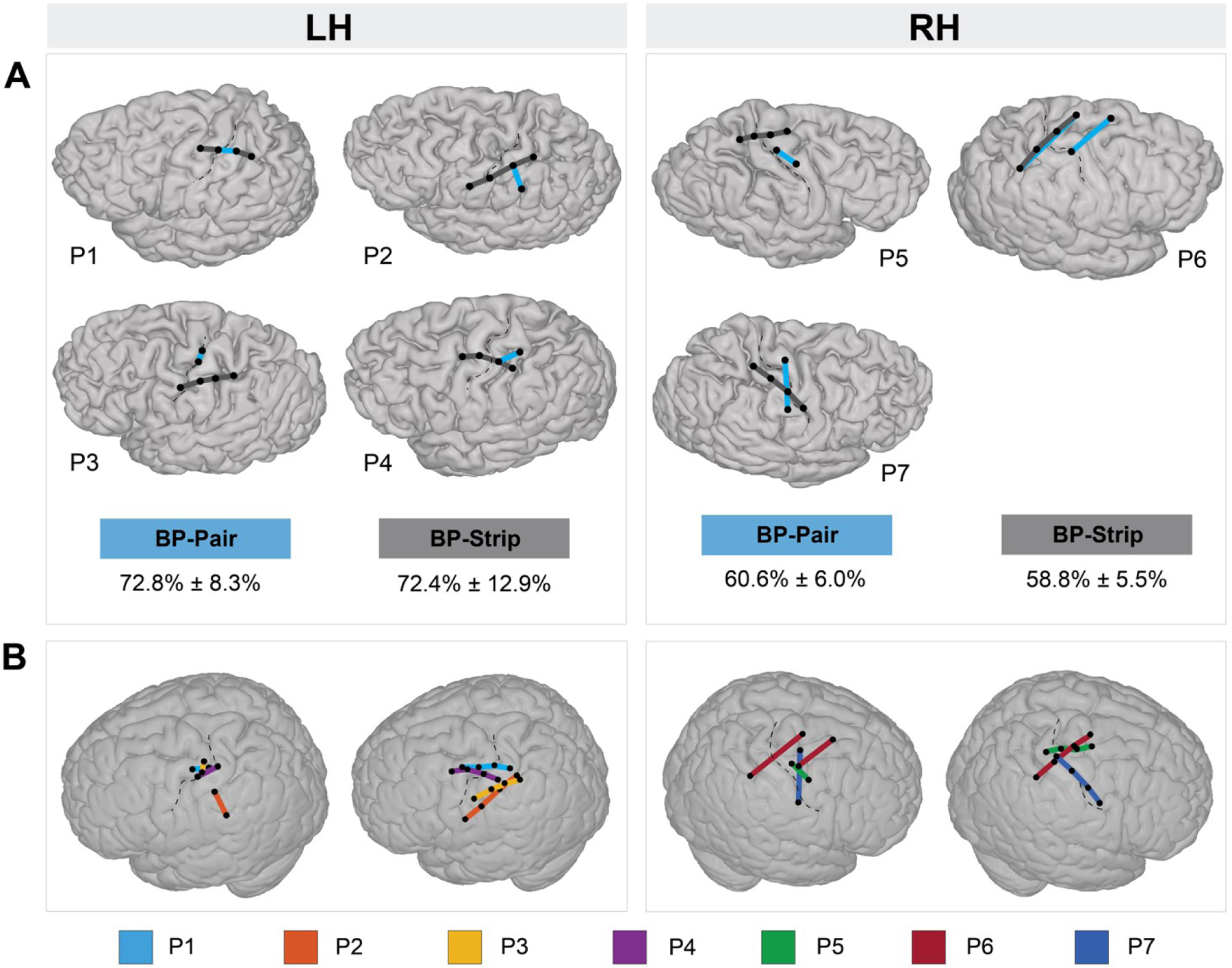
Objective.Electrocorticography (ECoG) based brain-computer interfaces (BCIs) can be used to restore communication in individuals with locked-in syndrome. In motor-based BCIs, the number of degrees-of-freedom, and thus the speed of the BCI, directly depends on the number of classes that can be discriminated from the neural activity in the sensorimotor cortex. When considering minimally invasive BCI implants, the size of the subdural ECoG implant must be minimized without compromising the number of degrees-of-freedom.Approach.Here we investigated if four hand gestures could be decoded using a single ECoG strip of four consecutive electrodes spaced 1 cm apart and compared the performance between a unipolar and a bipolar montage. For that we collected data of seven individuals with intractable epilepsy implanted with ECoG grids, covering the hand region of the sensorimotor cortex. Based on the implanted grids, we generated virtual ECoG strips and compared the decoding accuracy between (a) a single unipolar electrode (Unipolar Electrode), (b) a combination of four unipolar electrodes (Unipolar Strip), (c) a single bipolar pair (Bipolar Pair) and (d) a combination of six bipolar pairs (Bipolar Strip).Main results.We show that four hand gestures can be equally well decoded using 'Unipolar Strips' (mean 67.4 ± 11.7%), 'Bipolar Strips' (mean 66.6 ± 12.1%) and 'Bipolar Pairs' (mean 67.6 ± 9.4%), while 'Unipolar Electrodes' (61.6 ± 5.9%) performed significantly worse compared to 'Unipolar Strips' and 'Bipolar Pairs'.Significance.We conclude that a single bipolar pair is a potential candidate for minimally invasive motor-based BCIs and encourage the use of ECoG as a robust and reliable BCI platform for multi-class movement decoding.
Keywords: bipolar; brain–computer interface; electrocorticography; minimally invasive; sign language; unipolar.
© 2021 IOP Publishing Ltd.
Conflict of interest statement
Figures
Similar articles
-
Decoding hand gestures from primary somatosensory cortex using high-density ECoG.Neuroimage. 2017 Feb 15;147:130-142. doi: 10.1016/j.neuroimage.2016.12.004. Epub 2016 Dec 5. Neuroimage. 2017. PMID: 27926827 Free PMC article.
-
Functional MRI based simulations of ECoG grid configurations for optimal measurement of spatially distributed hand-gesture information.J Neural Eng. 2021 Feb 26;18(2):10.1088/1741-2552/abda0d. doi: 10.1088/1741-2552/abda0d. J Neural Eng. 2021. PMID: 33418549 Free PMC article.
-
Give me a sign: decoding four complex hand gestures based on high-density ECoG.Brain Struct Funct. 2016 Jan;221(1):203-16. doi: 10.1007/s00429-014-0902-x. Epub 2014 Oct 2. Brain Struct Funct. 2016. PMID: 25273279 Free PMC article.
-
A Review of Motor Brain-Computer Interfaces Using Intracranial Electroencephalography Based on Surface Electrodes and Depth Electrodes.IEEE Trans Neural Syst Rehabil Eng. 2024;32:2408-2431. doi: 10.1109/TNSRE.2024.3421551. Epub 2024 Jul 4. IEEE Trans Neural Syst Rehabil Eng. 2024. PMID: 38949928 Review.
-
The Potential for a Speech Brain-Computer Interface Using Chronic Electrocorticography.Neurotherapeutics. 2019 Jan;16(1):144-165. doi: 10.1007/s13311-018-00692-2. Neurotherapeutics. 2019. PMID: 30617653 Free PMC article. Review.
References
-
- Benabid AL, Costecalde T, Eliseyev A, Charvet G, Verney A, Karakas S, … Chabardes S (2019). An exoskeleton controlled by an epidural wireless brain–machine interface in a tetraplegic patient: a proof-of-concept demonstration. The Lancet Neurology, 18(12), 1112–1122. 10.1016/S1474-4422(19)30321-7 - DOI - PubMed
Publication types
MeSH terms
Grants and funding
LinkOut - more resources
Full Text Sources