. 2021 Sep 24;14(19):5540.
doi: 10.3390/ma14195540.

Helical Nanostructures of Ferroelectric Liquid Crystals as Fast Phase Retarders for Spectral Information Extraction Devices: A Comparison with the Nematic Liquid Crystal Phase Retarders

Affiliations

Helical Nanostructures of Ferroelectric Liquid Crystals as Fast Phase Retarders for Spectral Information Extraction Devices: A Comparison with the Nematic Liquid Crystal Phase Retarders

Marwan J AbuLeil et al. Materials (Basel). .

Abstract

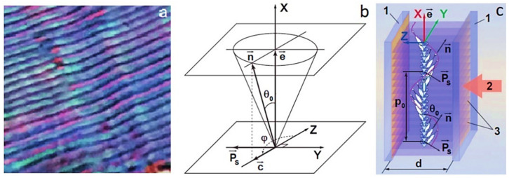
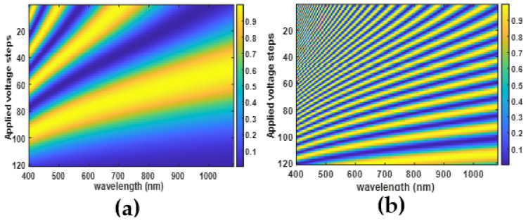
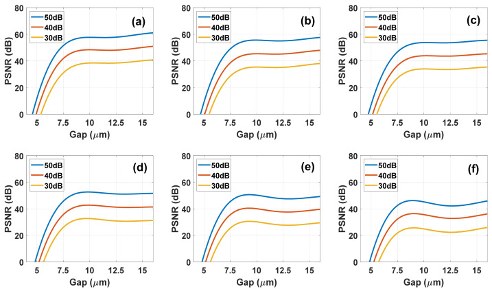
Extraction of spectral information using liquid crystal (LC) retarders has recently become a topic of great interest because of its importance for creating hyper- and multispectral images in a compact and inexpensive way. However, this method of hyperspectral imaging requires thick LC-layer retarders (50 µm-100 µm and above) to obtain spectral modulation signals for reliable signal reconstruction. This makes the device extremely slow in the case of nematic LCs (NLCs), since the response time of NLCs increases proportionally to the square of the LC-layer thickness, which excludes fast dynamic processes monitoring. In this paper, we explore two approaches for solving the speed problem: the first is based on the use of faster nanospiral ferroelectric liquid crystals as an alternative to NLCs, and the second is based on using a passive multiband filter and focuses on multispectral extraction rather than hyperspectral. A detailed comparative study of nematic and ferroelectric devices is presented. The study is carried out using a 9-spectral bands passive spectral filter, covering the visible and near-infrared ranges. We propose the concept of multispectral rather than hyperspectral extraction, where a small number of wavelengths are sufficient for specific applications.

Keywords: compressed sensing; inverse scattering; liquid crystal devices; spectral imaging.


Conflict of interest statement

The authors declare no conflict of interest.

Figures

Figure 1
Figure 1
(a) An image of the HSFLC in a polarizing microscope, image size is 80 μm × 80 μm [19]; (b) the location of the HSFLC director n in a separate smectic layer, the plane of which is parallel to YZ plane, Ps is the spontaneous polarization vector, c is c-director, e is the normal to the smectic layer plane, θ0 is the molecular tilt angle in smectic layers, φ is azimuth angle of the director in the plane of the smectic layer [20]; (c) the structure of HSFLC bounded by flat transparent and conductive substrates 1. Arrow 2 shows the direction along the planes of the smectic layers 3, which coincides with the direction of light propagation. The thickness of the HSFLC is designated as d [21].
Figure 2
Figure 2
Schematic structure of anti-parallel aligned NLC device. The left side presents the NLC device structure, the right part shows a zoom for the molecular orientation according to the axes (assuming that the alignment direction is along the x axis) and ϑz represents the director profile.
Figure 3
Figure 3
Simulation of spectral modulations of NLC devices using E7 NLC parameters at different applied voltages for two NLC thicknesses: (a) 5 μm and (b) 50 μm while the color of the fringes represents the transmission coefficient value.
Figure 4
Figure 4
(a) Dependences on the electric field of the effective birefringence ΔneffE (red circles) and the deviation of the main optical axis ΨdE (blue balls) of the planar-aligned liquid DHFLC-587-F7 with the helix pitch around 65 nm, developed in [73]. The measurements were carried out at 22 °C at a wavelength λ = 632.8 nm; (b) illustration of the biaxial transformation of the effective refractive index ellipsoid of the DHFLC in an electric field in a planar-aligned DHFLC cell (the same geometry as in Figure 1c). Numeral 1 denotes transparent conductive substrates, arrow 2 shows the direction of propagation of linearly polarized incident light, the same as in Figure 1c. All images are taken from [69].
Figure 5
Figure 5
(a) measured intensity I(E) of monochromatic light (λ = 532 nm) transmitted through the DHFLC cell (d = 107 μm) placed between crossed polarizers at β = 0. Ferroelectric liquid crystal FLC-618 described in [34] was used in experiments carried out and at 23 °C, the applied electric field frequency 7 Hz; (b) the effective birefringence ΔneffE+ and ΔneffE of the FLC-618 versus square of the applied electric field for its both polarities: ΔneffE+ (red balls) was measured for the positive polarity, while ΔneffE (blue circles) for the negative one.
Figure 6
Figure 6
(a) Dispersions of refractive indices of the FLC-618; (b) the main optical axis rotation angle of the FLC-618 versus the applied electric field. Measurements were carried out at 23 °C.
Figure 7
Figure 7
Spectral modulations of 131 µm DHFLC device while (a) represents the measured transmission for β=45 degrees; (b) shows the simulated transmission for β=45 degrees; (c) shows the simulated transmission for β=22.5 degrees while the color of the fringes represents the transmission coefficient value.
Figure 8
Figure 8
Frequency dependence of electrooptical response times τON and τOFF of the DHFLC cell based on FLC-618, d = 107 μm, T = 23 °C. The inset illustrates the applied voltage and electro-optical response waveforms.
Figure 9
Figure 9
Micrographs of textures of a planar-aligned 107-µm thick layer of the FLC-618 helical nanostructure (p0 = 105 nm) in a polarizing microscope, image size 250 µm × 200 µm. Dark field on the left: the axis of the FLC helix is directed along the plane of the polarizer of the microscope, i.e., β=0 ; the bright field on the right when the axis is at the angle of β = 45°.
Figure 10
Figure 10
Oscillogram of the electro-optical response in white light (upper curve) of the planar-aligned FLC-618, the layer thickness of which in the electro-optical DHFLC cell is 107 μm. The lower yellow curve is the applied alternating voltage with the amplitude of ±40 Volts.
Figure 11
Figure 11
(a) This graph shows the spectral transmission of a multi-channel spectral passive filter. The filter can be designed to transmit the wavelengths according to the specific application. (b) This figure depicts the breaking of the spectral transfer function of the filter to a set of spectra that can form any spectral signal which will pass through the filter. It should be noted that the spectral filter contains 9 spectral windows and now this is displayed as 9 different spectra (in different colors) that together form any spectral signal that reaches the detector. (c) Transpose matrix transition from channel weights to spectrum, in other words this is the matrix form of (b).
Figure 12
Figure 12
Simulation results of the reconstruction quality measured in PSNR, as function of the NLC E7 gap at different SNR as indicated for each curve values and different number of Voltages: (a) 56; (b) 28; (c) 19; (d) 14; (e) 12; (f) 10.
Figure 13
Figure 13
Simulated reconstructed spectra with the input signal is the blue curve and the red is the reconstructed ones using two different NLC E7 gaps, 6 µm for (ac) while 12 µm for (df) and different SNR values in dB: (a,d) 50; (b,e) 40; (c,f) 30. The number of voltages is 19.
Figure 14
Figure 14
Simulation results of the reconstruction quality measured in PSNR, as function of the DHFLC cell gap at different SNR as indicated for each curve values and different number of voltages: (a) 151; (b) 76; (c) 51; (d) 38; (e) 31; (f) 26.
Figure 15
Figure 15
Simulated reconstructed spectra with the input signal is the blue curve and the red is the reconstructed ones using two different DHFLC-618 gaps, 110 µm for (ac) while 153 µm for (df) and different SNR values in dB: (a,d) 50; (b,e) 40; (c,f) 30. The number of voltages is 51.
Figure 16
Figure 16
Simulated transmission matrix for different incidence angles: (a) NLC E7 at 0 deg; (b) is the averaged modulation of anti-parallel NLC E7 at 20° light-cone; (c) is the averaged modulation parallel NLC at 20° light-cone; (d) is the DHF FLC-618 at 0 deg; (e) is the averaged modulation of DHFLC at 20° light-cone.
Figure 17
Figure 17
Reconstruction quality measured in terms of PSNR versus the incidence angle: (a) is for cone of light; (b) is for off-axis collimated beam.

Similar articles

References

    1. Chen H., Lee J., Lin B., Chen S., Wu S. Liquid crystal display and organic light-emitting diode display: Present status and future perspectives. Nat. Publ. Group. 2018;7:17113–17168. doi: 10.1038/lsa.2017.168. - DOI - PMC - PubMed
    1. Beeckman J. Liquid-crystal photonic applications. Opt. Eng. 2011;50:81202. doi: 10.1117/1.3565046. - DOI
    1. Li Q., editor. Liquid Crystals beyond Displays. John Wiley & Sons, Inc.; Hoboken, NJ, USA: 2012.
    1. Ashkin A., Dziedzic J.M., Bjorkholm J.E., Chu S. Observation of a single-beam gradient force optical trap for dielectric particles. Opt. Lett. 1986;11:288. doi: 10.1364/OL.11.000288. - DOI - PubMed
    1. The Nobel Prize in Physics 2018. [(accessed on 10 September 2021)]. Available online: https://www.nobelprize.org/prizes/physics/2018/summary/%20No%20Title/

LinkOut - more resources