. 2021 Oct 3;21(19):6607.
doi: 10.3390/s21196607.

Monitoring of Large Diameter Sewage Collector Strengthened with Glass-Fiber Reinforced Plastic (GRP) Panels by Means of Distributed Fiber Optic Sensors (DFOS)

Affiliations

Monitoring of Large Diameter Sewage Collector Strengthened with Glass-Fiber Reinforced Plastic (GRP) Panels by Means of Distributed Fiber Optic Sensors (DFOS)

Paweł Popielski et al. Sensors (Basel). .

Abstract

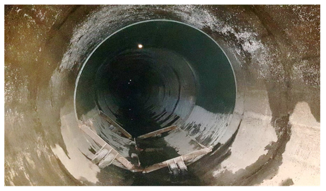
Diagnostics and assessment of the structural performance of collectors and tunnels require multi-criteria as well as comprehensive analyses for improving the safety based on acquired measurement data. This paper presents the basic goals for a structural health monitoring system designed based on distributed fiber optic sensors (DFOS). The issue of selecting appropriate sensors enabling correct strain transfer is discussed hereafter, indicating both limitations of layered cables and advantages of sensors with monolithic cross-section design in terms of reliable measurements. The sensor's design determines the operation of the entire monitoring system and the usefulness of the acquired data for the engineering interpretation. The measurements and results obtained due to monolithic DFOS sensors are described hereafter on the example of real engineering structure-the Burakowski concrete collector in Warsaw during its strengthening with glass-fiber reinforced plastic (GRP) panels.

Keywords: collector; concrete; cracks; displacements; distributed fiber optic sensing DFOS; glass fiber reinforced polymer GFRP; layered cables; monolithic sensors; strains; strengthening; tunnels.


Conflict of interest statement

The authors declare no conflict of interest.

Figures

Figure 1
Figure 1
The view of Burakowski concrete collector during its technical inspection.
Figure 2
Figure 2
GRP test panel inside a collector before installation.
Figure 3
Figure 3
Examples of sensing cable designs: (a) with plastic coating; (b) with metal coating and single or multiple plastic coatings; (c) with metal coating and additional metal reinforcing elements and with single or multiple plastic coatings.
Figure 4
Figure 4
The effect of slippage inside layered sensing cable when measuring crack opening in concrete member under axial tension. As the load increases, the crack peak is reduced, instead of higher. Blue—force of 6 kN, Red—force of 10 kN. When measured correctly, an increase in force should result in increase in the measured strain peak.
Figure 5
Figure 5
Cross-section of DFOS measurement sensor used for strain measurement. 1—monolithic core, 2—optic fiber [7].
Figure 6
Figure 6
Crack analysis in reinforced concrete beam using monolithic DFOS sensors. Sensor was embedded inside the beam at the height of main bottom reinforcement (courtesy by [8]). Graphs show strains development during increasing the load (local peaks correspond to cracks near to the bottom surface); (a) initial phase; (b) middle phase; (c) final phase.
Figure 7
Figure 7
Sensor locations along the collector.
Figure 8
Figure 8
Sensors used in the monitoring system. (a) Sensor A—EpsilonRebar, (b) Sensor B—EpsilonSensor [8].
Figure 9
Figure 9
(a) EpsilonRebars delivered to the site in coils; (b) arrangement of DFOS sensors (type A) in the cross section of the collector.
Figure 10
Figure 10
Spatial visualizations: (a) longitudinal sensors arrangement; (b) scheme of installation inside the groove filled with chemical anchor.
Figure 11
Figure 11
View of the sensor on the collector wall inside the groove during filling it with chemical anchor.
Figure 12
Figure 12
Examples of diagonal cracks of a collector concrete structure.
Figure 13
Figure 13
Scheme of DFOS sensors (type B) installation in the cracked section of collector.
Figure 14
Figure 14
Scheme of DFOS sensors arrangement in walls of the existing collector. I—section outside the loops, II—intersection of sensors A and B.
Figure 15
Figure 15
Strain profiles measured by sensor (T) along the test section showing the primary discontinuities in the concrete collector closing during strengthening process. Example section from 132 to 146 m. Measurement P01—after installation of GRP panels, P02—during grout injection, P03—after completed grout injection, P04—after filling the collector with sewage.
Figure 16
Figure 16
Relative vertical displacements (change in shape) of the collector after installation of GRP panels and grout injection.

References

    1. Gerbrandt J.L., Westman C.N. When a pipe breaks: Monitoring an emergency spill in the oil sands and documenting its erasure of indigenous interests in land. Extr. Ind. Soc. 2020;7:1301–1308. doi: 10.1016/j.exis.2020.07.012. - DOI
    1. Bednarz B. Numerical verification o the thickness of GRP Panels for modernization of large-diameter sewage collectors with non-circular cross-sections. In: Skoczko I., Krawczyk D.A., Szatyłowicz E., editors. Series of Monographs Vol. 38 Innovations, Sustainability, Modernity, Opennes—Water. Volume 38. Faculty of Civil and Enviromenal Engineering Białystok University of Technology; Bałystok, Poland: 2019. pp. 77–87.
    1. Nienartowicz B. Underground Infrastructure of Urban Areas 3. CRC Press; Leiden, The Netherlands: Balkema, Cop.; Avereest, The Netherlands: 2014. Analysis of selected aspects of the operation of pipelines renewed with the relining method on the basis of laboratory testing results; pp. 181–189.
    1. Bao X., Chen L. Recent Progress in Distributed Fiber Optic Sensors. Sensors. 2012;12:8601–8639. doi: 10.3390/s120708601. - DOI - PMC - PubMed
    1. Zhou D.P., Li W., Chen L., Bao X. Distributed temperature and strain discrimination with stimulated brillouin scattering and rayleigh backscatter in an optical fiber. Sensors. 2013;13:1836–1845. doi: 10.3390/s130201836. - DOI - PMC - PubMed

LinkOut - more resources