. 2021 Oct 5;21(19):6619.
doi: 10.3390/s21196619.

The Lightfield Microscope Eyepiece

Affiliations

The Lightfield Microscope Eyepiece

Nicolò Incardona et al. Sensors (Basel). .

Abstract

Lightfield microscopy has raised growing interest in the last few years. Its ability to get three-dimensional information about the sample in a single shot makes it suitable for many applications in which time resolution is fundamental. In this paper we present a novel device, which is capable of converting any conventional microscope into a lightfield microscope. Based on the Fourier integral microscope concept, we designed the lightfield microscope eyepiece. This is coupled to the eyepiece port, to let the user exploit all the host microscope's components (objective turret, illumination systems, translation stage, etc.) and get a 3D reconstruction of the sample. After the optical design, a proof-of-concept device was built with off-the-shelf optomechanical components. Here, its optical performances are demonstrated, which show good matching with the theoretical ones. Then, the pictures of different samples taken with the lightfield eyepiece are shown, along with the corresponding reconstructions. We demonstrated the functioning of the lightfield eyepiece and lay the foundation for the development of a commercial device that works with any microscope.

Keywords: 3D microscopy; FiMic; Fourier integral microscope; lightfield eyepiece; lightfield microscopy; plenoptic eyepiece.


Conflict of interest statement

The authors declare no conflict of interest. The funders had no role in the design of the study; in the collection, analyses, or interpretation of data; in the writing of the manuscript, or in the decision to publish the results.

Figures

Figure 1
Figure 1
Optical scheme of the Fourier integral microscope with the lightfield microscope eyepiece highlighted in blue. Π0 is the object plane, fOB is the focal length of the microscope objective, ΠAS is the plane of the aperture stop of the microscope objective. dTL is the distance from the aperture stop plane to the tube lens, fTL is the focal length of the tube lens. Π0 is the conjugate of Π0, namely the intermediate image plane. sF is the distance from the front focal plane of the eypiece to the first lens of the eyepiece, e is the distance between the lenses of the eyepiece, sF is the distance from the second lens of the eyepiece to the back focal plane of the eyepiece. ΠAS is the conjugate of ΠAS, namely the exit pupil plane, lEP is the distance from the back focal plane of the eyepiece to the exit pupil plane, fMLA is the focal length of the microlenses. Π0 is the conjugate of Π0, namely the image plane.
Figure 2
Figure 2
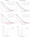
Comparison between two possible eyepiece systems: a single lens and a Ramsden eyepiece. Top line: the MTFs at the center of the FOV. Central line: the MTFs at the edge of the FOV. Bottom line: the lateral color displacement as a function of the lateral displacement in the FOV.
Figure 3
Figure 3
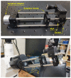
The proof-of-concept device. On the top, the device with all its parts indicated. On the bottom, the device inserted into the microscope.
Figure 4
Figure 4
Intrinsic MTF: the ideal and experimental MTF of the lightfield eyepiece when it is not inserted in the microscope.
Figure 5
Figure 5
Extrinsic MTFs: the ideal and experimental MTF of the entire system when the lightfield eyepiece is coupled to the host microscope. On the left, the MTF with the 20x objective. On the right, the MTF with the 40x objective.
Figure 6
Figure 6
Contrast values over working distance shift for both 20x and 40x objective. The triangles are the experimentally measured values, the dotted lines are the trend lines. The working distance shift has a value 0 when the USAF chart is at the object plane, it has negative values when the USAF chart is moved further from the objective and positive values when the USAF chart is moved closer to the objective.
Figure 7
Figure 7
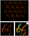
Cotton fibers. On the top, the entire frame registered by the device. On the bottom, the central perspective view and the depth map calculated from the lightfield image.
Figure 8
Figure 8
Living phytoplankton. On the left, the first frame of the video recorded through the lightfield eyepiece. On the right, the corresponding reconstruction: the Z projection and the orthogonal views are shown.
Figure 9
Figure 9
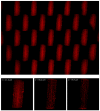
Hypocotyl of Arabidopsis Thaliana imaged with a water immersion objective. On the top, the entire frame registered by the device. On the bottom, the sample reconstructed at three different depths.

References

    1. Sheppard C., Cogswell C. Three-dimensional image formation in confocal microscopy. J. Microsc. 1990;159:179–194. doi: 10.1111/j.1365-2818.1990.tb04774.x. - DOI
    1. Kino G.S., Corle T.R. Confocal Scanning Optical Microscopy and Related Imaging Systems. Academic Press; Cambridge, MA, USA: 1996.
    1. Huisken J., Swoger J., Del Bene F., Wittbrodt J., Stelzer E.H. Optical sectioning deep inside live embryos by selective plane illumination microscopy. Science. 2004;305:1007–1009. doi: 10.1126/science.1100035. - DOI - PubMed
    1. Chen B.C., Legant W.R., Wang K., Shao L., Milkie D.E., Davidson M.W., Janetopoulos C., Wu X.S., Hammer J.A., Liu Z., et al. Lattice light-sheet microscopy: Imaging molecules to embryos at high spatiotemporal resolution. Science. 2014;346:1257998. doi: 10.1126/science.1257998. - DOI - PMC - PubMed
    1. Schermelleh L., Carlton P.M., Haase S., Shao L., Winoto L., Kner P., Burke B., Cardoso M.C., Agard D.A., Gustafsson M.G., et al. Subdiffraction multicolor imaging of the nuclear periphery with 3D structured illumination microscopy. Science. 2008;320:1332–1336. doi: 10.1126/science.1156947. - DOI - PMC - PubMed

LinkOut - more resources