Review
. 2022 Jan;34(1):e2105196.
doi: 10.1002/adma.202105196. Epub 2021 Oct 13.

Fiber-Based Biopolymer Processing as a Route toward Sustainability

Affiliations
Review

Fiber-Based Biopolymer Processing as a Route toward Sustainability

Chunmei Li et al. Adv Mater. 2022 Jan.

Abstract

Some of the most abundant biomass on earth is sequestered in fibrous biopolymers like cellulose, chitin, and silk. These types of natural materials offer unique and striking mechanical and functional features that have driven strong interest in their utility for a range of applications, while also matching environmental sustainability needs. However, these material systems are challenging to process in cost-competitive ways to compete with synthetic plastics due to the limited options for thermal processing. This results in the dominance of solution-based processing for fibrous biopolymers, which presents challenges for scaling, cost, and consistency in outcomes. However, new opportunities to utilize thermal processing with these types of biopolymers, as well as fibrillation approaches, can drive renewed opportunities to bridge this gap between synthetic plastic processing and fibrous biopolymers, while also holding sustainability goals as critical to long-term successful outcomes.

Keywords: cellulose; fibrous biopolymers; processing; silk; sustainability; thermal processing.


Figures

Figure 1.
Figure 1.. Sustainability Overview:
a) linear lifecycle of synthetic polymers and b) circular lifecycle of biopolymers.
Figure 2.
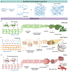
Figure 2.. Polymer structures and assemblies.
a) Illustration of the structure of synthetic thermoplastic polymers. b) Illustration of cellulose hierarchical structures. Hydrogen bonding promotes the self-assembly of poly-D-glucose to form nanofibers, where amorphous and crystalline regions are formed with different crystallinities. The nanofibers are bundled into microfibers, then assembled into cellulose fibers. c) Illustration of silk fibroin hierarchical structures, where polypeptides are assembled into β-sheets, α helices, and random coils via hydrogen bonding, resulting in two regions: amorphous and nanocrystalline. The silk nanofibers are then assembled into silk fibers. In combination with sericin, the silk fibers are formed into cocoons (Bombyx mori). d) Illustrations of hierarchical structures of chitin. The molecular structure of chitin starts with poly-acetylglucosamine, where the polymer chains self-assemble through hydrogen bonding to form nanofibers composed of amorphous and crystallin regions. The chitin nanofibers bundle together to form chitin fibers that lead to Bouligand (helicoidal) structures.
Figure 3.
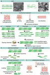
Figure 3.. Thermal properties and conventional processing methods of synthetic thermoplastic polymers and biopolymers.
a) Differential scanning calorimetry (DSC) curve for a genetic semi-crystalline thermoplastic polymer. The curve demonstrates that with increased temperature, synthetic polymers go through a glass transition at Tg, a cold crystallization process, and subsequently melting at Tm, until degradation at Td. b) Illustrations of four processing methods for thermoplastic polymers with thermal processing windows: compression molding, injection molding, extrusion molding, and 3D printing. c) Illustration of a DSC curve for a generic biopolymer, showing no clear Tg temperature or Tm before decomposition. d) illustrations of common solution and fibrillation-based processing methods to generate biopolymer-based particles, fibers, films, hydrogels, and sponges.
Figure 4.
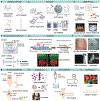
Figure 4.. Solution-based silk processing to fabricate materials.
a) Illustration of regenerated silk solution with high content of random coil structures. b) Designed functions are integrated into silk materials by adding dopants into aqueous silk solution. c) Strategies to guide silk refolding and modulate silk structure to fabricate silk-based materials. d) to l) Examples of multidimensional silk materials obtained via aqueous silk solution-based processing techniques. d) Nanodesk array fabricated by combined electron beam lithography and ion beam lithography. Reproduced with permission.[59] Copyright 2018, Wiley-VCH. e) Silk inverse opals fabricated by infiltrating silk solution into a pre-templated 3D poly(methyl methacrylate) (PMMA) or polystyrene (PS) sphere array. Reproduced by permission.[60] Copyright 2017, Wiley-VCH. f) Microspheres prepared by using a co-flow capillary device. Reproduced with permission.[61] Copyright 2014, Wiley-VCH. g) Silk/PAA composite needle with AF647-ovalbumin (OVA, blue) in silk tips and AF555-ovalbumin (red) in PAA pedestals. Silk tips were prepared by casting silk-OVA solution in microneedle mold followed by air drying. Reproduced with permission.[62] Copyright 2014, Wiley-VCH. i) Dissolvable silk film prepared by drop casting as substrate for conformal bioelectronics. Reproduced with permission.[63] Copyright 2010, Springer Nature. k) Silk vase prepared by extrusion-based 3D printing. Reproduced with permission.[64] Copyright 2020, Wiley-VCH. l) Injectable silk hydrogel containing doxorubicin prepared by sonication-induced gelation. Reproduced with permission. Copyright 2013, Wiley-VCH. n) Three-layered meniscus-shaped 3D porous scaffolds consisting of salt-leaching and free-drying scaffolds. Reproduced with permission.[65] Copyright 2011, Mary Ann Liebert, Inc. j) 3D bulk silk machined from silk bulk material prepared by self-assembly of silk solution. Reproduced with permission.[66] Copyright 2016, Elsevier.
Figure 5.
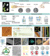
Figure 5.. Applications of silk-based materials through solution-based processing in regenerative medicine, drug delivery, optics and electronics.
a) 3D silk scaffolds used to generate long-term 3D tissue culture models. Cortical brain-like tissue after 9 weeks of culture (neurons labeled green, silk structure labled cyan). Reproduced with permission.[68] Copyright 2014, National Academy of Sciences. b) Porous silk microspheres for vocal tissue augmentation. Reproduced with permission.[70] Copyright 2019, Elsevier. c) Bioluminescence imaging of tumor regression in mice treated with doxorubicin-containing injectable silk hydrogels. Reproduced with permission.[72] Copyright 2013, Wiley-VCH. d) Schematic of formation of Dox-loaded magnetic silk nanoparticles for targeted therapy of multidrug-resistant cancer. Reproduced with permission.[82] Copyright 2014, Wiley-VCH. e) A 50 μm thick bent silk inverse opal (SIO) film showing different structural colors. f) SEM image of the surface of a SIO templated from the colloidal crystals composed of PS spheres with diameter of 300 nm. g) Patterned SIOs formed through selective exposure of SIO to water vapor or UV. SIO contracts uniformly isotropically with water vapor treatment or non-uniformly anisotropically after UV irradiation. Left shows floral pattern on SIO by selective exposure of masked SIO array to water vapor for different times. e to g), reproduced with permission.[60] Copyright 2017, Wiley-VCH. h) Photograph (top) and illustration (bottom) of silk-based transient electronic device. Reproduced with permission.[89] Copyright 2012, American Association for the Advancement of Science. i) Schematic of a mesoscopic memristor using silk film functionalized with silver nanoclusters as a switching layer. Reproduced with permission.[92] Copyright 2019, Wiley-VCH.
Figure 6.
Figure 6.. Cellulose dissolution, regeneration, material formats and advanced applications.
a) Illustration of cellulose dissolution from feedstock using green solvents and the dissolution mechanism of cellulose in ionic liquids. Reproduced with permission.[106] Copyright 2017, the Royal Society of Chemistry. b) Shaping and regeneration of cellulose materials from cellulose solution with the structural changes and the various shaping and regeneration methods, including solvent evaporation to form films, chemical or physical crosslinking to form hydrogels, spinning to form cellulose fibers, and spinning drop atomization, dropping, spinning disc atomization to generate cellulose microbeads. c) Examples of material formats of regenerated cellulose. Fibers, reproduced with permission.[124] Copyright 2007, WILEY-VCH. Films, reproduced with permission.[94] Copyright 2019, American Chemical Society. Microbeads, reproduced with permission.[125] Copyright 2005, American Chemical Society. Hydrogels, reproduced with permission.[126] Copyright 2007, WILEY-VCH. d) Examples of advanced applications of regenerated cellulose. Conductive regenerated cellulose films, reproduced with permission.[121] Copyright 2019, Elsevier. Optical fibers, reused with open access.[123] Copyright 2019. The Author(s). Wearable electronic textiles, reused with permission.[122] Copyright 2019, the Royal Society of Chemistry.
Figure 7.
Figure 7.. Preparation of nanocellulose.
a) Illustrations and TEM images of CNF (left) and CNC (right). Reused under open access.[154] b) Mechanical treatment for CNF preparation including high pressure homogenization, high-intensity ultrasonication, grinding, and microfluidizer. c-e) Pretreatment methods including chemical, enzymatic, and ionic liquid treatments are combined with mechanical treatment for CNF preparation. f) Chemical treatment to prepare cellulose nanocrystals (CNC) through oxidation and acid hydrolysis. The dots indicate new functional groups through chemical reaction. g) Enzymatic treatment to remove amorphous domains to make CNC. h) Ionic liquids (ILs) pretreatment to swell cellulose fibers for further chemical treatment to make CNC. i) Mechanical treatment to remove amorphous regions to make CNC, including ball milling, ultrasonication, and high pressure homogenization.
Figure 8.
Figure 8.. Assembly of nanocellulose based materials and their applications.
a) Methods to prepare nanocellulose hydrogels via electrostatic interactions, ionic interactions, chemical crosslinking, and self-assembly. b) Strategies to add functions to nanocellulose hydrogels including preparation of stimuli responsive hydrogels reused under permission,[160] copyright 2019, Wiley-VCH, self-healing materials, reproduced with permission,[161] copyright 2019, Springer Nature, and 3D scaffold, reproduce with permission,[162] copyright 2019, The Royal Society of Chemistry. c) Applications of nanocellulose hydrogels as sensors, in tissue engineering, drug delivery, as contact lenses,[163] reproduced with permission, Copyright 2019, Elsevier, as tissue adhesives, reproduced with permission,[164] copyright 2020, American Chemical Society. d) Methods to make nanocellulose based films/membranes via drop casting on a substrate (CNC can be used as a filler) or to make free standing films through the paper making methods. e) Methods to prepare films utilizing the crystal characteristics of nanocellulose with a demonstration of shear induced CNC films,[165] reproduced with permission, copyright 2013, American Chemical Society, and the self-assembly method to make photonic nanocellulose films, reproduced with permission,[156], copyright 2019, Elsevier. f) Applications of nanocellulose- based films including thin film transistors,[166] reproduced with permission, copyright 2014, Wiley-VCH, fuel cells, reproduced with permission,[167] copyright 2016, American Chemical Society, in water treatment, reproduced with permission,[168] copyright 2018, Wiley-VCH, and as photonics, reproduced with open access,[169] copyright 2016, The Authors. g) Methods to prepare nanocellulose microbeads via spray drying and spray freeze drying. h) Applications of nanocellulose microbeads as absorbents for water treatment, as drug delivery vehicles, and in cosmetics. i) Methods to make nanocellulose fibers by wet spinning, dry spinning, and flow-based methods, j) Applications of nanocellulose based fibers as textiles, and as membrane materials.
Figure 9.
Figure 9.. Preparation, assembly and application of fibrillated silk fibers.
a) Examples of fibrillated silk fibers in the form of microfibers, nanofibers and nanoribbons. b) Chemical and mechanical treatments to prepare fibrillated silk fibers. c) Silk microfibers prepared by partial dissolution of degummed B. mori fiber were assembled into fiber bundles through dry spinning. Three-dimensional cell patterns generated on yarn-like spiral silk fibers. Fluorescent images show preferential alignment of human dermal fibroblasts (green) along the axes of the regenerated silk fibers (red). Reproduced with open access.[177] d) Silk nanofibers prepared by liquid exfoliation was assembled into silk membranes. SEM images and photos (from left to right): Cross-section SEM image of the liquid exfoliated SNF membrane at low and high magnifications. Photo of a SNF membrane with excellent transparency. CdSeS/ZnS quantum dot patterned SNF membranes prepared via masked vacuum-filtration under UV light. Photo of gold single crystal nanoplatelet patterned SNF membranes prepared by vacuum filtration of SNF suspensions through a vacuum filtration membrane with a pre-deposited gold single crystal nanoplatelets pattern. Photo shows SNF based flexible electronic devices deformed with the deformation of a pig ear. Reused with permission.[176] Copyright 2016, Wiley-VCH. e) SNFs prepared by treatment of DES solvent assisted by mild mechanical disintegration. TEM image shows SNG morphology. SNFs ink directly written on TOCN and DEChN membranes. Photos of SNF-written TOCN membranes before (top) and after (bottom) immersion in Ponceau S solutions. Photos of SNF-written DEChN membranes before (top) and after (bottom) immersion in toluidine solutions. Reproduced with permission.[181] Copyright 2020, American Chemical Society.
Figure 10.
Figure 10.. Thermoplastic processing of regenerated silk films.
Illustration of the two nanoimprinting processes: a) hot embossing and b) room-temperature embossing. c) SEM image of silk film imprinted with a periodic array of chromium nanoparticles (200 nm diameter and 30 nm height) separated by 250 nm. a) to c), reproduced by permission.[190] Copyright 2010, Wiley-VCH. d) Illustration of the protein-protein imprinting (PiP) and replication mechanism. The pattern in a crystallized silk fibroin master (yellow) was transferred to an untreated, unpatterned film by pressing the two stacking layers on a heated substrate at 120°C for 60 s, with pressure of about 50 psi. SEM images showing the original pattern of the master film and the inversed pattern in the untreated film. The high-throughput generation of the red pattern realized by duplicating the patterns using each generation to imprint the next. e) Conformal protein-protein imprinting using a nonplanar aluminum tool (grey). f) Photos of lens (9.8 mm radius of curvature, 15 mm diameter) and the imprinted lens (inset) fabricated by conformal PiP. g) Imprinted film transferred to skin as an example of a curved biological surface. d) to g), reproduced with permission.[192] Copyright 2013, Wiley-VCH. h) Illustration of lamination method for silk film welding. The patterned or unpatterned amorphous silk layer is placed between crystallized device layers and then subjected to treatment at 120°C and 80 Psi of pressure for ≈30 s. i) Tensile testing performed on two crystallized silk films (red) welded together by amorphous silk film (blue). j) Protection of a magnesium antenna fabricated on a silk substrate via encapsulation in a silk pocket or direct application of a silk passivation layer on the surface. k) Array of 10 × 10 holes of 100 μm diameter produced by spatial control of the welding. A bubble in the cross section of the assembled structure. h) to k), reproduced with permission.[191] Copyright 2016, Wiley-VCH.
Figure 11.
Figure 11.. Thermal Processing of Silk.
a) Schematic of transformation of natural silk fibers into silk-based bulk materials by thermal processing. b) Comparison of the specific strength and stiffness of silk bulk materials with those of natural silk materials and other materials, such as bone, synthetic polymers, ceramics, and metals and alloys. Reproduced with permission.[22] Copyright 2020, Springer Nature. c-f) Photographs of silk objects fabricated by the thermal processing method with/without post-machining. g) Silk structures prepared by thermal forming. h) Schematic of mechanism for structural transition of ASN during thermal processing. a, d, g and h), reproduced with permission.[21] Copyright 2020, Springer Nature. i) Comparison of solution-based (aqueous and organic solvent) and thermal-based processing routes to prepare bulk silk materials. Reproduced with permission.[11] Copyright 2020, AIP publishing.

References

    1. https://www.statista.com/statistics/282732/global-production-of-plastics....
    1. Cozzi L, Gould T, International Energy Agency 2015.
    1. Corcoran PL, Environ. Sci.: Process. Impacts 2015, 17, 1363. - PubMed
    1. Lau WWY, Shiran Y, Bailey RM, Cook E, Stuchtey MR, Koskella J, Velis CA, Godfrey L, Boucher J, Murphy MB, Thompson RC, Jankowska E, Castillo Castillo A, Pilditch TD, Dixon B, Koerselman L, Kosior E, Favoino E, Gutberlet J, Baulch S, Atreya ME, Fischer D, He KK, Petit MM, Sumaila UR, Neil E, Bernhofen MV, Lawrence K, Palardy JE, Science 2020, 369, 1455. - PubMed
    1. Coates GW, Getzler YDYL, Nat. Rev. Mater 2020, 5, 501.

LinkOut - more resources