. 2021 Sep 30:8:716451.
doi: 10.3389/frobt.2021.716451. eCollection 2021.

An Adaptive Mechatronic Exoskeleton for Force-Controlled Finger Rehabilitation

Affiliations

An Adaptive Mechatronic Exoskeleton for Force-Controlled Finger Rehabilitation

Thomas Dickmann et al. Front Robot AI. .

Abstract

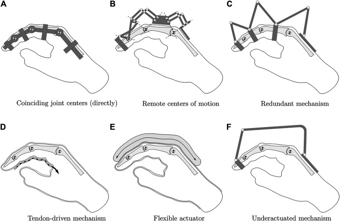
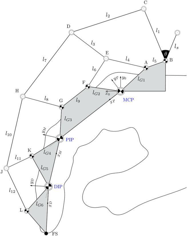
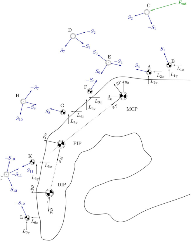
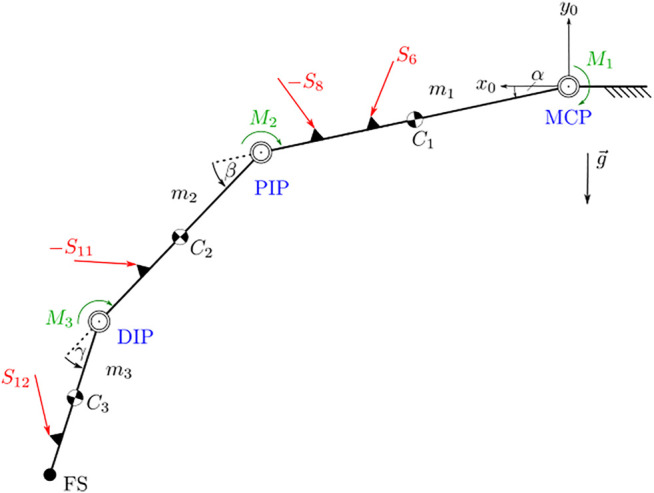
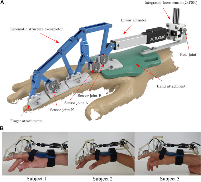
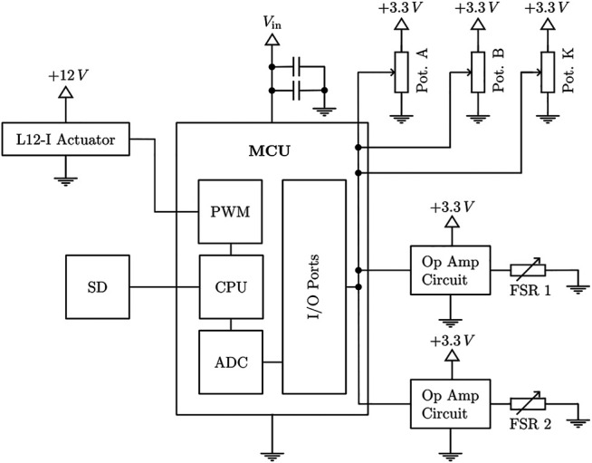
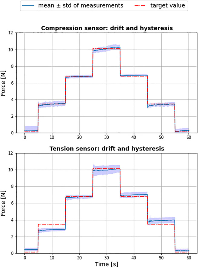
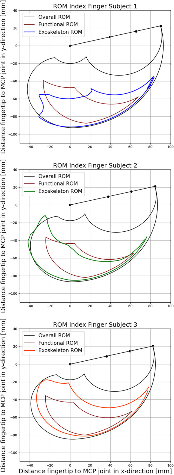
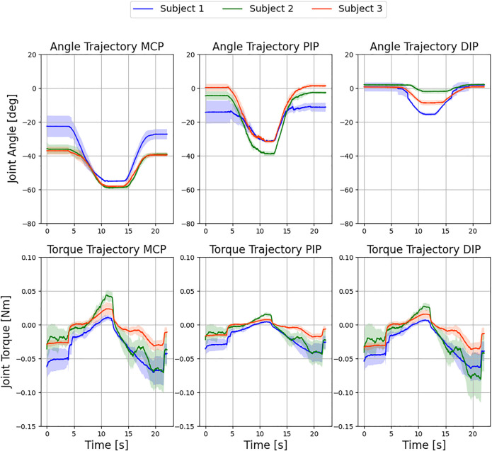
This paper presents a novel mechatronic exoskeleton architecture for finger rehabilitation. The system consists of an underactuated kinematic structure that enables the exoskeleton to act as an adaptive finger stimulator. The exoskeleton has sensors for motion detection and control. The proposed architecture offers three main advantages. First, the exoskeleton enables accurate quantification of subject-specific finger dynamics. The configuration of the exoskeleton can be fully reconstructed using measurements from three angular position sensors placed on the kinematic structure. In addition, the actuation force acting on the exoskeleton is recorded. Thus, the range of motion (ROM) and the force and torque trajectories of each finger joint can be determined. Second, the adaptive kinematic structure allows the patient to perform various functional tasks. The force control of the exoskeleton acts like a safeguard and limits the maximum possible joint torques during finger movement. Last, the system is compact, lightweight and does not require extensive peripherals. Due to its safety features, it is easy to use in the home. Applicability was tested in three healthy subjects.

Keywords: adaptive control; assisstive technologies; exoskeletal analysis; exoskeletal assist system; interaction; manipulator; rehabilitate.


Conflict of interest statement

The authors declare that the research was conducted in the absence of any commercial or financial relationships that could be construed as a potential conflict of interest.

Figures

FIGURE 1
FIGURE 1
Hand exoskeleton kinematic options, modified from Heo et al. (2012).
FIGURE 2
FIGURE 2
Linkage structure of the exoskeleton system as an extension to Jo and Bae (2017). The finger joints are marked in blue. Areas marked in grey are considered as rigid bodies within the structure.
FIGURE 3
FIGURE 3
Orientation of points P, M, and N relative to a world frame as defined in Figure 2.
FIGURE 4
FIGURE 4
Orientation of all acting forces in space as the basis for equilibrium equations for each joint.
FIGURE 5
FIGURE 5
Kinematic connection between actor and exoskeleton. The force F act generates the external momentum M act around point B.
FIGURE 6
FIGURE 6
Dynamic model of the unconstrained finger. The finger joints are marked in blue. Areas marked in black are considered as rigid bodies within the structure. External forces are marked in red.
FIGURE 7
FIGURE 7
Rendering (A) and application of the real system (B) of the exoskeleton. The rendering contains all the information about the exoskeleton and its components. In the bottom row, the exoskeleton is attached to the index finger of three individual test subjects.
FIGURE 8
FIGURE 8
Interconnection of all electric components of the exoskeleton system.
FIGURE 9
FIGURE 9
Exploded view of the force sensing resistor (FSR) sensor integration. The setup ensures an orthogonal application of the applied forces on the resistor in tension and compression direction.
FIGURE 10
FIGURE 10
Control loop of the exoskeleton. The controller follows a predefined position signal in the inner control loop and is limited by a torque-based two-point control.
FIGURE 11
FIGURE 11
Result of force sensor tests for tension (sensor 1) and compression (sensor 2) over ten independent test cycles.
FIGURE 12
FIGURE 12
Comparison of the exoskeleton Range of Motion (ROM) with active and functional movement space for the three subjects respectively according to Bain et al. (2015).
FIGURE 13
FIGURE 13
Evaluation of exemplary movement of the three fingers with the exoskeleton over six independent test cycles. Displayed are the resulting mean ± standard deviation over all cycles for the respective subjects. No control intervention occurred.
FIGURE 14
FIGURE 14
Control intervention for subject 1 during a flexing movement of the index finger with a torque limit of 0.1 Nm at the actuator over three independent test cycles. Displayed are the resulting mean ± standard deviation over all cycles. The finger hits a force sensitive plate at 7 s, which measures a maximum external force to the fingertip of 1.53 ± 0.1 N.

References

    1. Aragón-Martínez A., Arias-Montiel M., Lugo-González E., Tapia-Herrera R. (2020). Two-finger Exoskeleton with Force Feedback for a mobile Robot Teleoperation. Int. J. Adv. Robotic Syst. 17, 172988141989564. 10.1177/1729881419895648 - DOI
    1. Bain G. I., Polites N., Higgs B. G., Heptinstall R. J., McGrath A. M. (2015). The Functional Range of Motion of the finger Joints. The J. Hand Surg. Eur. volume 40, 406–411. 10.1177/1753193414533754 - DOI - PubMed
    1. Birch B., Haslam E., Heerah I., Dechev N., Park E. J. (2008). Design of a Continuous Passive and Active Motion Device for Hand Rehabilitation. IEEE Eng. Med. Biol. Soc. Conf. 2008, 4306–4309. 10.1109/IEMBS.2008.4650162 - DOI - PubMed
    1. Carbone G., Gerding E. C., Corves B., Cafolla D., Russo M., Ceccarelli M. (2020). Design of a Two-DOFs Driving Mechanism for a Motion-Assisted finger Exoskeleton. Appl. Sci. 10, 2619. 10.3390/app10072619 - DOI
    1. Cempini M., Cortese M., Vitiello N. (2015). A Powered finger–thumb Wearable Hand Exoskeleton with Self-Aligning Joint Axes. IEEE/ASME Trans. Mechatronics 20, 705–716. 10.1109/TMECH.2014.2315528 - DOI