Review
. 2021 Sep 24;13(10):1551.
doi: 10.3390/pharmaceutics13101551.

Polyelectrolyte Encapsulation and Confinement within Protein Cage-Inspired Nanocompartments

Affiliations
Review

Polyelectrolyte Encapsulation and Confinement within Protein Cage-Inspired Nanocompartments

Qing Liu et al. Pharmaceutics. .

Abstract

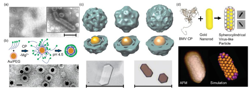
Protein cages are nanocompartments with a well-defined structure and monodisperse size. They are composed of several individual subunits and can be categorized as viral and non-viral protein cages. Native viral cages often exhibit a cationic interior, which binds the anionic nucleic acid genome through electrostatic interactions leading to efficient encapsulation. Non-viral cages can carry various cargo, ranging from small molecules to inorganic nanoparticles. Both cage types can be functionalized at targeted locations through genetic engineering or chemical modification to entrap materials through interactions that are inaccessible to wild-type cages. Moreover, the limited number of constitutional subunits ease the modification efforts, because a single modification on the subunit can lead to multiple functional sites on the cage surface. Increasing efforts have also been dedicated to the assembly of protein cage-mimicking structures or templated protein coatings. This review focuses on native and modified protein cages that have been used to encapsulate and package polyelectrolyte cargos and on the electrostatic interactions that are the driving force for the assembly of such structures. Selective encapsulation can protect the payload from the surroundings, shield the potential toxicity or even enhance the intended performance of the payload, which is appealing in drug or gene delivery and imaging.

Keywords: electrostatic interaction; nanocoating; nanocompartment; polyelectrolyte; protein cage; self-assembly.


Conflict of interest statement

The authors declare no conflict of interest.

Figures

Figure 1
Figure 1
Structures of protein cages highlighted in this review (not drawn to scale, blue color indicates the 12 pentamers and gray color indicates the 20 hexamers in (ac)): (a) Brome mosaic virus (BMV) (PDB 1JS9). (b) Cowpea chlorotic mottle virus (CCMV) (PDB 1CWP). (c) Red clover necrotic mosaic virus (RCNMV) (PDB 6MRM) and (d) lumazine synthase from Aquifex aeolicus (AaLS) (PDB 1HQK). Blue color indicates three protein subunits.
Figure 2
Figure 2
BMV VLPs assembled around diverse templates. (a) TEM images of BMV rod-like particles templated by a calf thymus dsDNA. Scale bar: 100 nm. Reprinted from [33]. Copyright (1969) with permission from Elsevier. (b) Top panel: The proposed BMV VLP formation templated by carboxylate-modified AuNPs. Bottom panel: A representative TEM image of BMV VLPs encapsulating 12 nm AuNPs. Scale bar: 20 nm. Reprinted with permission from [35]. Copyright (2006) American Chemical Society. (c) Top and middle panel: 3D reconstructions of BMV VLPs templated by AuNPs of different sizes (from left to right: 6, 9 and 12 nm). Bottom panel: transmission optical images of (left) R3BMV crystals and (right) VLP12 crystals. Scale bar: 100 μm. Reprinted with permission from [36]. Copyright (2007) National Academy of Sciences. (d) Top panel: Schematic illustration and TEM images of BMV VLPs formed around gold nanorods. Bottom panel: The structure imaged by AFM and the corresponding simulated structure. Reprinted with permission from [37]. Copyright (2018) American Chemical Society.
Figure 3
Figure 3
CCMV VLPs templated by DNA nanostructures. (a) Representative TEM images of CCMV capsids templated by a 500 bp dsDNA with bp:CP dimer ratios of (from left to right): 1:1, 7:1, 14:1 and 28:1. White arrows mark the hemispherical caps. Scale bar: 50 nm. Reprinted with permission from [48]. Copyright (2006) American Chemical Society. (b) Left panel: Schematic illustration of CCMV capsid assemblies templated by DNA micelles and the proposed approaches for drug loading. Right panel: Representative TEM images of (left) assembled CCMV VLPs and (right) free DNA micelles. Scale bar: 40 nm. Reprinted with permission from [50]. Copyright (2010) American Chemical Society. (c) Left panel: Schematic illustration of CCMV CP coated DNA origami and the subsequent cellular delivery. Right panel: TEM images and the corresponding illustrative models (insets) of (left) the original rectangular DNA origami, (middle) the rolled tubes of CCMV CP coated DNA origami and (right) unwrapped CCMV CP coated DNA origami. Scale bar: 200 nm. Reprinted with permission from [53]. Copyright (2014) American Chemical Society.
Figure 4
Figure 4
CCMV VLPs assembled around synthetic polymers and amphiphiles. (a) Schematic pathway of CCMV-PEG assembly templated by PSS and the characterization result from TEM measurement. Scale bar: 50 nm. Reprinted with permission from [54]. Copyright (2009) American Chemical Society. (b) Schematic presentation of the morphological manipulation of CCMV VLPs through the template structure transition that is controlled by NaCl concentration and the corresponding TEM images. Scale bar: 200 nm. Reprinted with permission from [60]. Copyright (2011) American Chemical Society. (c) Schematic illustration of the encapsulation of ZnPc dyes into CCMV VLPs and the cell images (bottom left panel) in the presence and (bottom right panel) in the absence of ZnPc-loaded capsids. Both images are the overlap of fluorescence images and transmission images of RAW 264.7 macrophage cells. Scale bar: 100 μm. Reprinted with permission from [62]. Copyright (2011) American Chemical Society. (d) Spherical and tubular CCMV VLPs templated by tailor-made Pt(II) amphiphiles. Scale bar: 50 nm. Reprinted with permission from [63]. Copyright (2018) American Chemical Society.
Figure 5
Figure 5
RCNMV VLPs templated by NPs. (Top panel): schematic representation of the templated assembly of RCNMV on NPs. (Bottom panel): TEM images of RCNMV VLPs containing magnetic CoFe2O4 NPs of different sizes. Scale bar: 200 nm. Reprinted with permission from [71]. Copyright (2007) American Chemical Society.
Figure 6
Figure 6
AaLS mutants and the sequestration of cationic cargos. (a) Schematic illustration of the loading of a R10-tagged HIV protease into the non-quasi-equivalent AaLS variant, AaLS-13, and the EM images of (left) AaLS-neg, (middle) AaLS-13 and (right) AaLS-13 coproduced with HIV protease-R10 (white and black arrows indicate empty and protease-loaded cages, respectively). Scale bar: 100 nm. From [76]. Reprinted with permission from AAAS. (b) Schematic illustration of the two approaches to load AaLS-13 with GFP(+36), and the characterization results (chromatogram and TEM) of (left) empty and (right) loaded AaLS-13. In both chromatogram graphs, black lines indicate protein absorption and red dots indicate the relative fluorescence of individual fractions. Scale bar: 100 nm. Reprinted with permission from [77]. Copyright (2012) American Chemical Society.
Figure 7
Figure 7
DNA nanostructures coated with proteins through electrostatic interactions. (a) Top panel: Schematic representation of DNA nanostructures coated with protein polymers. Bottom panel: Corresponding AFM images of DNA nanostructures coated with protein polymer. Scale bar: 50 nm. Reprinted with permission from [114]. Copyright (2017) American Chemical Society. (b) Top panel: Schematic illustration of the 60HB origami coated with BSA-G2 and the subsequent shielding effect against DNAase. Bottom panel: Confocal images of HEK293 cells after transfection with BSA-G2-coated 60HB for 12 h. The left panel is the green AlexaFluor 488 of origami channel, the middle panel is red LysoTracker, and the right panel contains the overlap of the left and middle panel and DAPI-stained nuclei. Scale bar: 50 μm. Reproduced with permission from [118].
Figure 8
Figure 8
Experimental and simulated demonstrations of protein coated NPs. (a) Adsorption of (top) plain HSA, (middle) HSAsuc and (bottom) HSAam onto DHLA-QDs as a function of protein concentrations and the corresponding schematic depictions of the hydrodynamic radii increase as a result of the protein adsorption. Reprinted with permission from [129]. Copyright (2014) American Chemical Society. (b) Simulated time sequence of the snapshots of the interactions between macrophage cell membranes and positively charged NPs. Left panel: in the absence of serum proteins. Right panel: in the presence of serum proteins. Reproduced with permission from [130].

References

    1. Yeates T.O., Crowley C.S., Tanaka S. Bacterial Microcompartment Organelles: Protein Shell Structure and Evolution. Annu. Rev. Biophys. 2010;39:185–205. doi: 10.1146/annurev.biophys.093008.131418. - DOI - PMC - PubMed
    1. Gabashvili A.N., Chmelyuk N.S., Efremova M.V., Malinovskaya J.A., Semkina A.S., Abakumov M.A. Encapsulins—Bacterial Protein Nanocompartments: Structure, Properties, and Application. Biomolecules. 2020;10:966. doi: 10.3390/biom10060966. - DOI - PMC - PubMed
    1. Tanaka S., Sawaya M.R., Yeates T.O. Structure and Mechanisms of a Protein-Based Organelle in Escherichia coli. Science. 2010;327:81–84. doi: 10.1126/science.1179513. - DOI - PubMed
    1. Siu K., Chen R.P., Sun Q., Chen L., Tsai S., Chen W. Synthetic Scaffolds for Pathway Enhancement. Curr. Opin. Biotechnol. 2015;36:98–106. doi: 10.1016/j.copbio.2015.08.009. - DOI - PubMed
    1. Uchida M., Klem M.T., Allen M., Suci P., Flenniken M., Gillitzer E., Varpness Z., Liepold L.O., Young M., Douglas T. Biological Containers: Protein Cages as Multifunctional Nanoplatforms. Adv. Mater. 2007;19:1025–1042. doi: 10.1002/adma.200601168. - DOI

LinkOut - more resources