Review
. 2021 Oct 25;10(1):216.
doi: 10.1038/s41377-021-00658-8.

Augmented reality and virtual reality displays: emerging technologies and future perspectives

Affiliations
Review

Augmented reality and virtual reality displays: emerging technologies and future perspectives

Jianghao Xiong et al. Light Sci Appl. .

Abstract

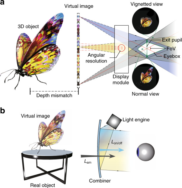
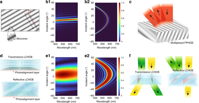
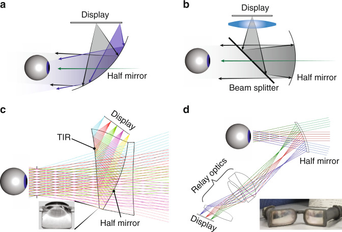
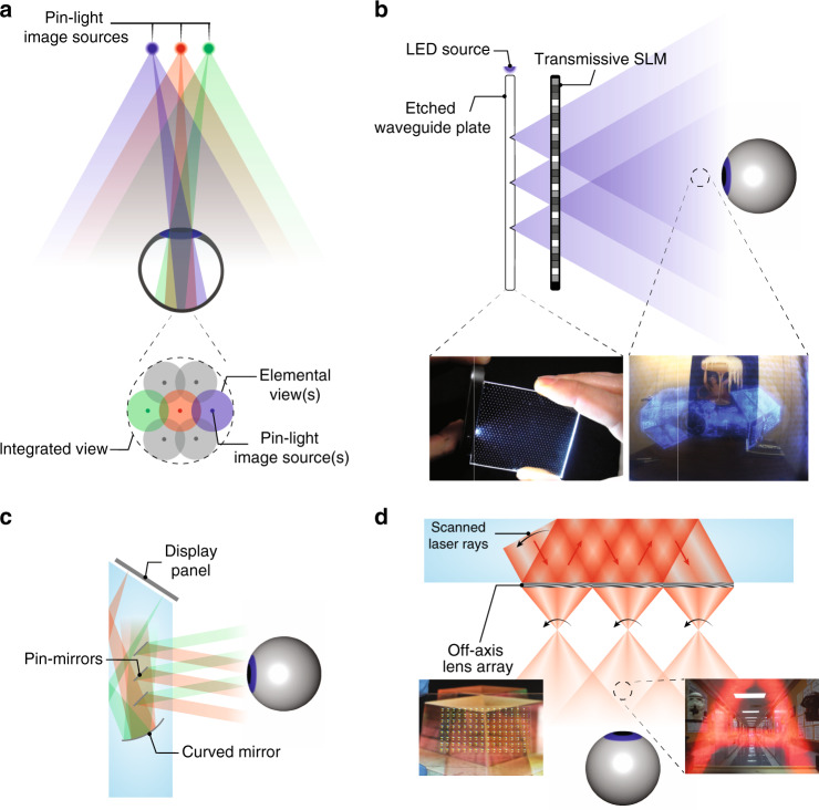
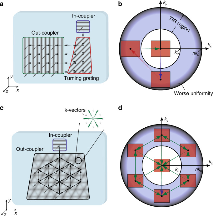
With rapid advances in high-speed communication and computation, augmented reality (AR) and virtual reality (VR) are emerging as next-generation display platforms for deeper human-digital interactions. Nonetheless, to simultaneously match the exceptional performance of human vision and keep the near-eye display module compact and lightweight imposes unprecedented challenges on optical engineering. Fortunately, recent progress in holographic optical elements (HOEs) and lithography-enabled devices provide innovative ways to tackle these obstacles in AR and VR that are otherwise difficult with traditional optics. In this review, we begin with introducing the basic structures of AR and VR headsets, and then describing the operation principles of various HOEs and lithography-enabled devices. Their properties are analyzed in detail, including strong selectivity on wavelength and incident angle, and multiplexing ability of volume HOEs, polarization dependency and active switching of liquid crystal HOEs, device fabrication, and properties of micro-LEDs (light-emitting diodes), and large design freedoms of metasurfaces. Afterwards, we discuss how these devices help enhance the AR and VR performance, with detailed description and analysis of some state-of-the-art architectures. Finally, we cast a perspective on potential developments and research directions of these photonic devices for future AR and VR displays.


Conflict of interest statement

The authors declare no competing interests.

Figures

Fig. 1
Fig. 1. Schematic of some emerging optical technologies applied in AR/VR.
The left side illustrates HOEs and lithography-based devices. The right side shows the challenges in VR and architectures in AR, and how the emerging technologies can be applied
Fig. 2
Fig. 2. Illustration of display parameters.
a Schematic of a VR display defining FoV, exit pupil, eyebox, angular resolution, and accommodation cue mismatch. b Sketch of an AR display illustrating ACR
Fig. 3
Fig. 3. Formation and properties of HOEs.
a Schematic of the formation of PPHOE. Simulated efficiency plots for b1 transmissive and b2 reflective PPHOEs. c Working principle of multiplexed PPHOE. d Formation and molecular configurations of LCHOEs. Simulated efficiency plots for e1 transmissive and e2 reflective LCHOEs. f Illustration of polarization dependency of LCHOEs
Fig. 4
Fig. 4. Properties of lithography-enabled micro-LEDs and metasurfaces.
a Illustration of flip-chip bonding technology. b Simulated IQE-LED size relations for red and blue LEDs based on ABC model. c Comparison of EQE of different LED sizes with and without KOH and ALD side wall treatment. d Angular emission profiles of LEDs with different sizes. Metasurfaces based on e resonance-tuning, f non-resonance tuning and g combination of both. h Replication master and i replicated SRG based on nanoimprint lithography. Reproduced from a ref. with permission from AIP Publishing, b ref. with permission from PNAS, c ref. with permission from IOP Publishing, d ref. with permission from AIP Publishing, e ref. with permission from OSA Publishing f ref. with permission from AAAS g ref. with permission from AAAS and h, i ref. with permission from OSA Publishing
Fig. 5
Fig. 5. Schemes to reduce the form factor of a VR display.
a Schematic of a basic VR optical configuration. b Achromatic metalens used as VR eyepiece. c VR based on curved display and lenslet array. d Basic working principle of a VR display based on pancake optics. e VR with pancake optics and Fresnel lens array. f VR with pancake optics based on purely HOEs. Reprinted from b ref. under the Creative Commons Attribution 4.0 License. Adapted from c ref. with permission from IEEE, e ref. and f ref. under the Creative Commons Attribution 4.0 License
Fig. 6
Fig. 6. Addressing VAC in VR.
Working principles of a depth switching PBL module based on a active addressing and b passive addressing. c A four-depth multifocal display based on time multiplexing. d A two-depth multifocal display based on polarization multiplexing. Reproduced from c ref. with permission from OSA Publishing and d ref. with permission from OSA Publishing
Fig. 7
Fig. 7. Different types of light engines in AR displays.
a RGB micro-LED microdisplays combined by a trichroic prism. b QD-based micro-LED microdisplay. c Micro-OLED display with 4032 PPI. Working principles of d LCoS, e DMD, and f MEMS-LBS display modules. Reprinted from a ref. with permission from IEEE, b ref. with permission from Chinese Laser Press, c ref. with permission from Jon Wiley and Sons, d ref. with permission from Spring Nature, e ref. with permission from Springer and f ref. under the Creative Commons Attribution 4.0 License
Fig. 8
Fig. 8. AR combiners based on geometric optical designs.
a Single freeform surface as the combiner. b Birdbath optics with a beam splitter and a half mirror. c Freeform TIR prism with a compensator. d Relay optics with a half mirror. Adapted from c ref. with permission from OSA Publishing and d ref. with permission from OSA Publishing
Fig. 9
Fig. 9. Maxwellian-type AR Combiners.
a Schematic of the working principle of Maxwellian displays. Maxwellian displays based on b SLM and laser diode light source and c MEMS-LBS with a steering mirror as additional modulation method. Generation of depth cues by d computational digital holography and e scanning of steering mirror to produce multiple views. Adapted from b, d ref. and c, e ref. under the Creative Commons Attribution 4.0 License
Fig. 10
Fig. 10. Methods of pupil duplication and pupil steering.
a Schematic of duplicating (or shift) viewpoint by modulation of incident light. Light modulation by b multiple laser diodes, c HOE lens array, d steering mirror and e grating or beam splitters. f Pupil duplication with multiplexed PPHOE. g Pupil steering with LCHOE. Reproduced from c ref. under the Creative Commons Attribution 4.0 License, e ref. with permission from OSA Publishing, f ref. with permission from OSA Publishing and g ref. with permission from OSA Publishing
Fig. 11
Fig. 11. Illustration of pin-light displays.
a Schematic drawing of the working principle of pin-light display. b Pin-light display utilizing a pin-light source and a transmissive SLM. c An example of pin-mirror display with a birdbath optics. d SWD system with LBS image source and off-axis lens array. Reprinted from b ref. under the Creative Commons Attribution 4.0 License and d ref. with permission from OSA Publishing
Fig. 12
Fig. 12. Working principles of diffractive waveguide combiners.
Schematics of waveguide combiners based on a SRGs, b PPGs and c PVGs. Reprinted from a ref. with permission from OSA Publishing, b ref. with permission from John Wiley and Sons and c ref. with permission from OSA Publishing
Fig. 13
Fig. 13. Schemes for 2D EPE.
a Schematic of 2D EPE based on two consecutive 1D EPEs. Gray/black arrows indicate light in air/TIR. Black dots denote TIRs. b k-diagram of the two-1D-EPE scheme. c Schematic of 2D EPE with a 2D hexagonal grating d k-diagram of the 2D-grating scheme
Fig. 14
Fig. 14. Artifacts of diffractive waveguide.
Sketches of formations of a light leakage, b see-through ghost and c rainbow. d Analysis of rainbow formation with k-diagram
Fig. 15
Fig. 15. Geometric waveguide combiner.
a Schematic of the system configuration. b Geometric waveguide with five partial mirrors. c Image photos demonstrating system FoV. Adapted from b, c ref. with permission from OSA Publishing
Fig. 16
Fig. 16. Skew-mirror waveguide combiner.
a System configuration. b Diagram demonstrating how multiplexed PPGs resemble the behavior of a mirror. Photos showing c the system and d image. e Picture demonstrating effective system FoV. Adapted from ce ref. with permission from ITE

References

    1. Cakmakci O, Rolland J. Head-worn displays: a review. J. Disp. Technol. 2006;2:199–216. doi: 10.1109/JDT.2006.879846. - DOI
    1. Zhan T, et al. Augmented reality and virtual reality displays: perspectives and challenges. iScience. 2020;23:101397. doi: 10.1016/j.isci.2020.101397. - DOI - PMC - PubMed
    1. Rendon AA, et al. The effect of virtual reality gaming on dynamic balance in older adults. Age Ageing. 2012;41:549–552. doi: 10.1093/ageing/afs053. - DOI - PubMed
    1. Choi S, Jung K, Noh SD. Virtual reality applications in manufacturing industries: past research, present findings, and future directions. Concurrent Eng. 2015;23:40–63. doi: 10.1177/1063293X14568814. - DOI
    1. Li X, et al. A critical review of virtual and augmented reality (VR/AR) applications in construction safety. Autom. Constr. 2018;86:150–162. doi: 10.1016/j.autcon.2017.11.003. - DOI