. 2022 Apr 1;57(4):212-221.
doi: 10.1097/RLI.0000000000000835.

First In-Human Results of Computed Tomography Angiography for Coronary Stent Assessment With a Spectral Photon Counting Computed Tomography

Affiliations

First In-Human Results of Computed Tomography Angiography for Coronary Stent Assessment With a Spectral Photon Counting Computed Tomography

Sara Boccalini et al. Invest Radiol. .

Abstract

Objectives: The aim of this study is to compare the image quality of in vivo coronary stents between an energy integrating detectors dual-layer computed tomography (EID-DLCT) and a clinical prototype of spectral photon counting computed tomography (SPCCT).

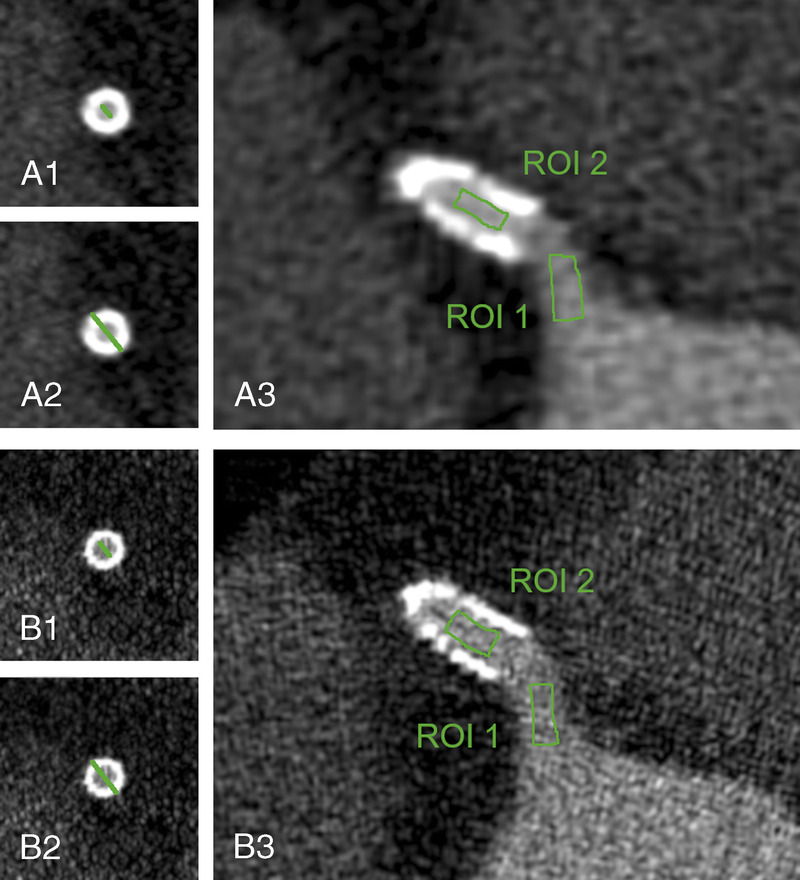
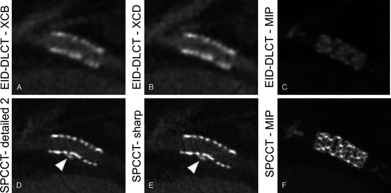
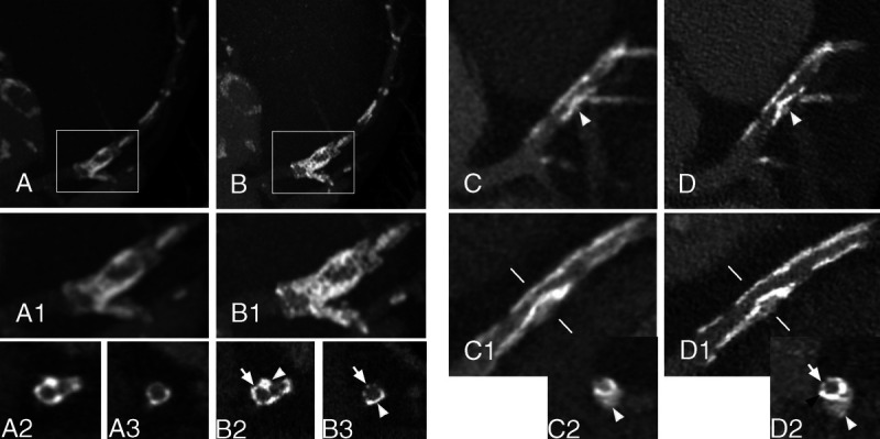
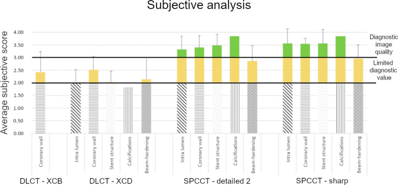
Materials and methods: In January to June 2021, consecutive patients with coronary stents were prospectively enrolled to undergo a coronary computed tomography (CT) with an EID-DLCT (IQon, Philips) and an SPCCT (Philips). The study was approved by the local ethical committee and patients signed an informed consent. A retrospectively electrocardiogram-gated acquisition was performed with optimized matching parameters on the 2 scanners (EID-DLCT: collimation, 64 × 0.625 mm; kVp, 120, automatic exposure control with target current at 255 mAs; rotation time, 0.27 seconds; SPCCT: collimation, 64 × 0.275 mm; kVp, 120; mAs, 255; rotation time, 0.33 seconds). The injection protocol was the same on both scanners: 65 to 75 mL of Iomeron (Bracco) at 5 mL/s. Images were reconstructed with slice thickness of 0.67 mm, 512 matrix, XCB (Xres cardiac standard) and XCD (Xres cardiac detailed) kernel, iDose 3 for EID-DLCT and 0.25-mm slice thickness, 1024 matrix, Detailed 2 and Sharp kernel, and iDose 6 for SPCCT. Two experienced observers measured the proximal and distal external and internal diameters of the stents to quantify blooming artifacts. Regions of interest were drawn in the lumen of the stent and of the upstream coronary artery. The difference (Δ S-C) between the respective attenuation values was calculated as a quantification of stent-induced artifacts on intrastent image quality. For subjective image quality, 3 experienced observers graded with a 4-point scale the image quality of different parameters: coronary wall before the stent, stent lumen, stent structure, calcifications surrounding the stent, and beam-hardening artifacts.

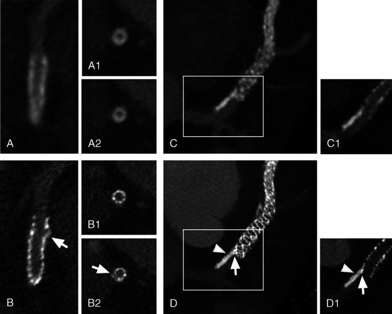
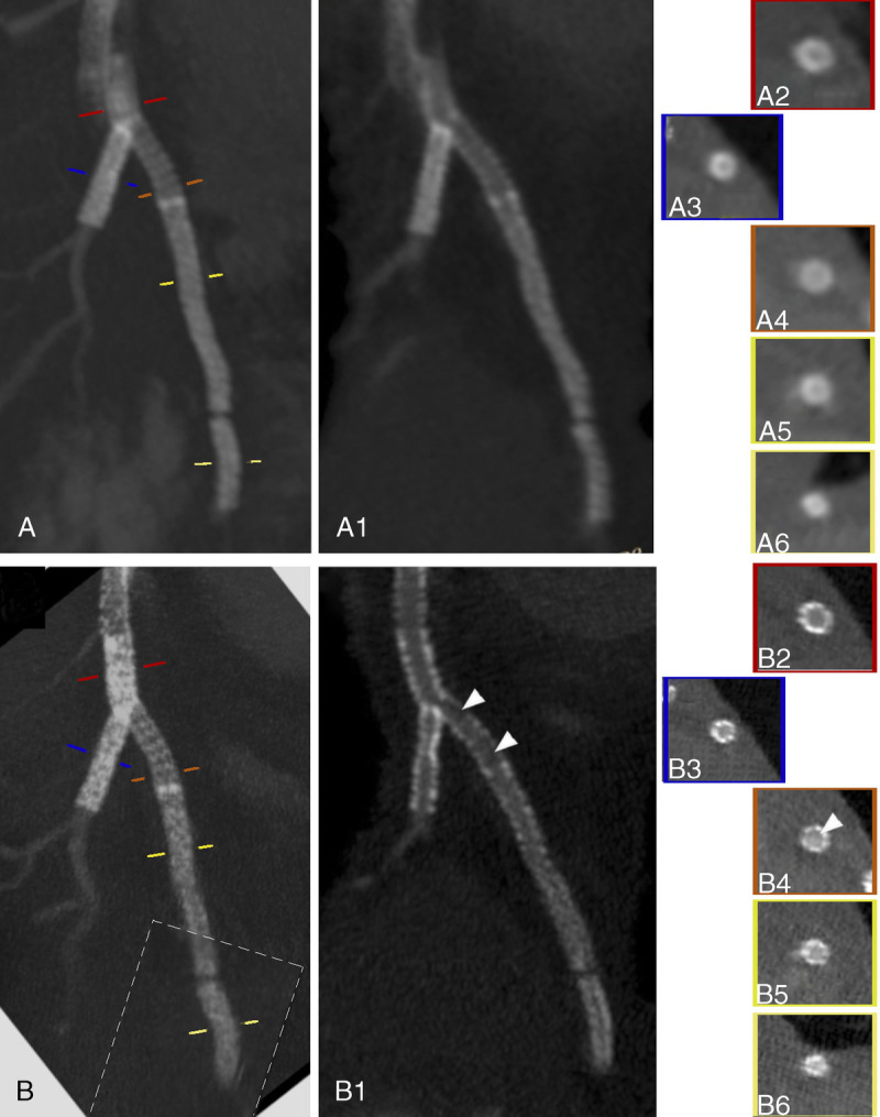
Results: Eight patients (age, 68 years [interquartile range, 8]; all men; body mass index, 26.2 kg/m2 [interquartile range, 4.2]) with 16 stents were scanned. Five stents were not evaluable owing to motion artifacts on the SPCCT. Of the remaining, all were drug eluting stents, of which 6 were platinum-chromium, 3 were cobalt-platinum-iridium, and 1 was stainless steel. For 1 stent, no information could be retrieved. Radiation dose was lower with the SPCCT (fixed CT dose index of 25.7 mGy for SPCCT vs median CT dose index of 35.7 [IQ = 13.6] mGy; P = 0.02). For 1 stent, the internal diameter was not assessable on EID-DLCT. External diameters were smaller and internal diameters were larger with SPCCT (all P < 0.05). Consequently, blooming artifacts were reduced on SPCCT (P < 0.05). Whereas Hounsfield unit values within the coronary arteries on the 2 scanners were similar, the Δ S-C was lower for SPCCT-Sharp as compared with EID-DLCT-XCD and SPCCT-Detailed 2 (P < 0.05). The SPCCT received higher subjective scores than EID-DLCT for stent lumen, stent structure, surrounding calcifications and beam-hardening for both Detailed 2 and Sharp (all P ≤ 0.05). The SPCCT-Sharp was judged better for stent structure and beam-hardening assessment as compared with SPCCT-Detailed 2.

Conclusion: Spectral photon counting CT demonstrated improved objective and subjective image quality as compared with EID-DLCT for the evaluation of coronary stents even with a reduced radiation dose.


Conflict of interest statement

Conflicts of interest and sources of funding: European Union Horizon 2020 research and innovation program under grant agreement no. 668142.

Figures

FIGURE 1
FIGURE 1
Panels A1-A2 and B1-B2 show how internal (A1 and B1) and external (A2 and B2) stent diameters have been measured on EID-DLCT (A) and SPCCT (B). Panels A3 and B3 illustrate how the free-hand ROIs have been drawn on EID-DLCT (A) and SPCCT (B) inside the coronary artery upstream the stent (ROI 1) and inside the lumen of the stent (ROI 2). Images are displayed in the window level and window width used for objective analysis, as defined in the methodology.
FIGURE 2
FIGURE 2
A synergy 3.5 × 12 mm stent placed in the proximal circumflex artery of a 72-year-old man depicted with EID-DLCT (A, B, and C) and SPCCT (D, E, and F). The structure of the stent is difficult to assess on both EID-DLCT multiplanar images reconstructed with both kernels (A: EID-DLCT-XCB; B: EID-DLCT-XCD) as well as on the EID-DLCT maximum intensity projection (MIP) (C) image while being clearly defined on SPCCT multiplanar (D: SPCCT-Detailed 2; E: SPCCT-Sharp) and MIP (F) images. The EID-DLCT also failed to depict a small calcification adjacent of the stent, nicely shown by SPCCT (D and E: arrowheads).
FIGURE 3
FIGURE 3
Stent extremities evaluation. Panels A (EID-DLCT-XCD) and B (SPCCT-Sharp) show a 3 × 30 mm Resolute Onyx stent of the proximal left anterior descending (LAD) in a 63-year-old patient. Long axis images of the proximal extremity of the stent are quite different between the 2 CT systems: whereas the outer border of the stent seems regular on EID-DLCT (A), an irregularity is clearly seen on SPCCT (B: arrow). Cross-axial images of the stent (at the proximal extremity of the stent (A1 and B1) and at the level of the irregularity (A2 and B2) showed a similarly homogeneous and blurry stent contour on EID-DLCT (A1 and A2). On the contrary, SPCCT nicely showed regular stent struts at the extremity (B1) and a hyperdense linear image protruding from the stent border (B2: arrow) at the level of the irregularity, suggesting a disrupted strut. Panels C (EID-DLCT-XCD) and D (SPCCT-Sharp) show the proximal extremity of a 3 × 48 mm Synergy stent of the proximal LAD in a 52-year-old patient. A maximum intensity projection (MIP) (C) reconstruction of the EID-DLCT showed a calcification of the upstream coronary wall, but its relationship with the stent was difficult to assess even when looking more closely on a multiplanar reconstruction (C1, corresponding to the white box on C). SPCCT images (D: MIP; D1: multiplanar reconstruction corresponding to the white box on D) not only allowed to depict sharp images of the stent struts and the coronary calcification (arrowheads) but also clearly showed that the proximal extremity of the stent was dislocated and pushed towards the center of the artery by the calcification (arrows).
FIGURE 4
FIGURE 4
EID-DLCT-XCD (A) and SPCCT-Sharp (B) curved planar reformation with (A and B) and without (A1 and B1) maximum intensity projection and cross-sectional images (A2-A6 and B2-B6) show the 4 stents of a 70-year-old man: a 3.5 × 24 mm Bioss Lim of the proximal left anterior descending (LAD) (orange line on A and B, A4 and B4), 2 Resolute Onyx stents of 2.5 × 30 mm (yellow line on A and B, A5 and B5), and 2.25 × 12 mm (light yellow line on A and B, A6 and B6) of the distal LAD as well as a 3 × 38 mm Synergy stent (blue line on A and B, A3 and B3) of the first diagonal branch. The latest has been deployed with a Y configuration, thus realizing a few millimeters of stent-in-stent (red line on A and B, A2 and B2). Even disregarding the proximal part of the first stent of the LAD that showed marked motion artifacts, the EID-DLCT system does not allow correct visualization of any of the stent lumina. On the contrary, SPCCT allows visualization of the stent struts and their lumina, suggesting the presence of restenosis on the first Resolute Onyx (arrowheads). The dotted-line box on B shows where an image reconstructed from a different phase of the cardiac cycle has been pasted for display.
FIGURE 5
FIGURE 5
Stent calcifications. Panels A (EID-DLCT-XCD) and B (SPCCT-Sharp) show a DES of the left anterior descending (LAD), extending over the origin of the diagonal, of a 69-year-old man deployed in 2007. On maximum intensity projection (MIP) (A and A1; A1 corresponds to the white box in A) and cross-axial (A2 and A3 at the level of the origin of the diagonal and a bit further downstream, respectively) reconstructions of the EID-DLCT, some hyperdense images on the walls of the coronary images could represent either calcifications or struts since the stent structure is undistinguishable. Corresponding images on SPCCT (MIP in B and B1; B1 corresponds to the white box in B; cross-sectional in B2 and B3) nicely show the stent struts (arrows) encrusted with calcifications (arrowheads). In panels C (EID-DLCT-XCD) and D (SPCCT-Sharp), a 3.5 × 12 mm Synergy stent of the LAD, extending over the origin of the diagonal, implanted 5 months before the CT scans. The stent had been placed over a rather voluminous calcification (white arrowheads) that is deforming the stent lumen as it is visible on EID-DLCT (C, C1, and C2; C2: cross-axial image at the level of the white lines on C1) as well as on corresponding SPCCT images (D, D1, and D2). The lumen of the stent is hard to assess on EID-DLCT, whereas it is clearly reduced in caliber but patent on SPCCT. Furthermore, on the SPCCT cross-axial image (D2), the stent struts are nicely visible on 1 side (arrow), whereas on the other side, the calcification has 1 peripheral less dense component (white arrowhead) and a denser layer closer to the stent (black arrow).
FIGURE 6
FIGURE 6
Average subjective scores.

References

    1. Knuuti J Wijns W Saraste A, et al. . 2019 ESC guidelines for the diagnosis and management of chronic coronary syndromes. Eur Heart J. 2020;41:407–477. doi:10.1093/eurheartj/ehz425. - DOI - PubMed
    1. Collet JP Thiele H Barbato E, et al. . 2020 ESC guidelines for the management of acute coronary syndromes in patients presenting without persistent ST-segment elevation. Eur Heart J. 2021;42:1289–1367. doi:10.1093/eurheartj/ehaa575. - DOI - PubMed
    1. Mahnken AH. CT imaging of coronary stents: past, present, and future. ISRN Cardiol. 2012;2012:139823. doi:10.5402/2012/139823. - DOI - PMC - PubMed
    1. Dai T, Wang JR, Hu PF. Diagnostic performance of computed tomography angiography in the detection of coronary artery in-stent restenosis: evidence from an updated meta-analysis. Eur Radiol. 2018;28:1373–1382. doi:10.1007/s00330-017-5097-0. - DOI - PubMed
    1. de Graaf FR Schuijf JD van Velzen JE, et al. . Diagnostic accuracy of 320-row multidetector computed tomography coronary angiography to noninvasively assess in-stent restenosis. Invest Radiol. 2010;45:331–340. doi:10.1097/RLI.0b013e3181dfa312. - DOI - PubMed

Publication types