

Cerebral aneurysm flow diverter modeled as a thin inhomogeneous porous medium in hemodynamic simulations
- PMID: 34717230
- PMCID: PMC9372908
- DOI: 10.1016/j.compbiomed.2021.104988
Cerebral aneurysm flow diverter modeled as a thin inhomogeneous porous medium in hemodynamic simulations
Abstract
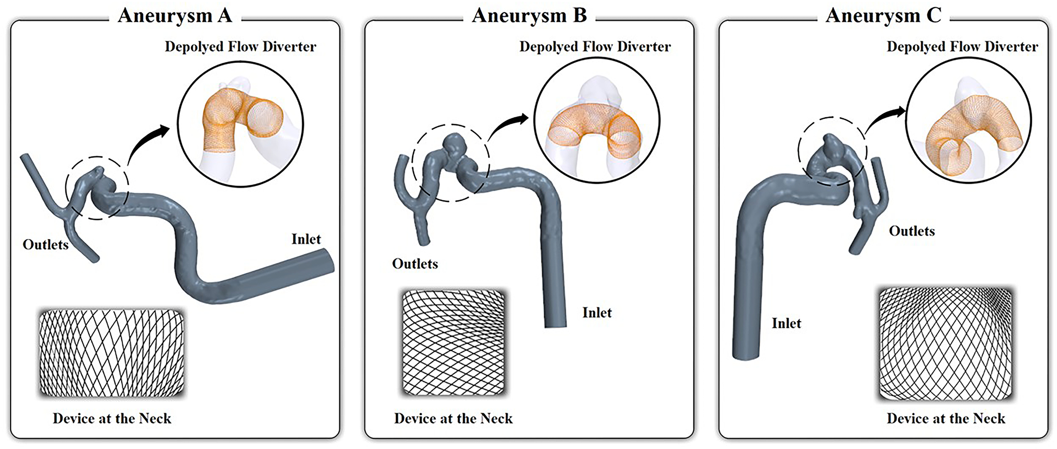
Rapid and accurate simulation of cerebral aneurysm flow modifications by flow diverters (FDs) can help improving patient-specific intervention and predicting treatment outcome. However, when FD devices are explicitly represented in computational fluid dynamics (CFD) simulations, flow around the stent wires must be resolved, leading to high computational cost. Classic porous medium (PM) methods can reduce computational expense but cannot capture the inhomogeneous FD wire distribution once implanted on a cerebral artery and thus cannot accurately model the post-stenting aneurysmal flow. We report a novel approach that models the FD flow modification as a thin inhomogeneous porous medium (iPM). It improves over the classic PM approaches in two ways. First, the FD is more appropriately treated as a thin screen, which is more accurate than the classic 3D-PM-based Darcy-Forchheimer relation. Second, pressure drop is calculated cell-by-cell using the local FD geometric parameters across an inhomogeneous PM. We applied the iPM technique to simulating the post-stenting hemodynamics of three patient-specific aneurysms. To test its accuracy and speed, we compared the results from the iPM technique against CFD simulations with explicit FD devices. The iPM CFD ran 500% faster than the explicit CFD while achieving 94%-99% accuracy; thus, iPM is a promising clinical bedside modeling tool to assist endovascular interventions with FD and stents.
Keywords: CFD Simulation; Intracranial aneurysm; Porous media; Stent modeling; Stent simulation.
Copyright © 2021. Published by Elsevier Ltd.
Figures


References
-
- Augsburger L, Reymond P, Rufenacht DA and Stergiopulos N Intracranial stents being modeled as a porous medium: flow simulation in stented cerebral aneurysms. Ann Biomed Eng 39: 850–863, 2011. - PubMed
-
- Biondi A, Janardhan V, Katz JM, Salvaggio K, Riina HA and Gobin YP Neuroform stent-assisted coil embolization of wide-neck intracranial aneurysms: strategies in stent deployment and midterm follow-up. Neurosurgery 61: 460–469, 2007. - PubMed
-
- Carman PC Flow of gases through porous media. 1956.
-
- Dazeo N, Dottori J, Boroni G and Larrabide I A comparative study of porous medium CFD models for flow diverter stents: Advantages and shortcomings. Int J Numer Method Biomed Eng 34: e3145, 2018. - PubMed
Publication types
MeSH terms
Grants and funding
LinkOut - more resources
Full Text Sources
Medical
Miscellaneous
