

doi: 10.1140/epjc/s10052-021-09298-z.
Epub 2021 Jun 12.
The design of the n2EDM experiment: nEDM Collaboration
Affiliations
- PMID: 34720721
- PMCID: PMC8550164
- DOI: 10.1140/epjc/s10052-021-09298-z
Item in Clipboard
The design of the n2EDM experiment: nEDM Collaboration
Eur Phys J C Part Fields.
2021.
Abstract
We present the design of a next-generation experiment, n2EDM, currently under construction at the ultracold neutron source at the Paul Scherrer Institute (PSI) with the aim of carrying out a high-precision search for an electric dipole moment of the neutron. The project builds on experience gained with the previous apparatus operated at PSI until 2017, and is expected to deliver an order of magnitude better sensitivity with provision for further substantial improvements. An overview is of the experimental method and setup is given, the sensitivity requirements for the apparatus are derived, and its technical design is described.
© The Author(s) 2021.
Figures

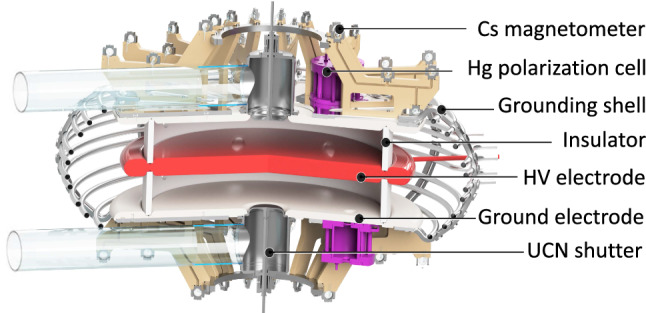
Cut through the central part of the n2EDM apparatus. Two vertically stacked storage (Ramsey spin-precession) chambers, filled with polarized UCNs and Hg atoms, are embedded in the same vertical magnetic field , but with opposite electric-field directions

Schematic view (not to scale) of the UCNs’ path a while filling the precession chambers, and b following the Ramsey cycle, when transporting UCNs towards the spin-sensitive detectors for counting

The asymmetry as a function of the applied frequency . The points represent experimental data where each point is a measurement cycle with a precession time of performed with the nEDM apparatus in September 2017 with the standard value of the magnetic field nT corresponding to a Larmor precession frequency of 30.2235 Hz. The error bars are smaller than the size of the points. The line is the fit to the data using the function from Eq. 2. The vertical bars show the position of the four “working points” used in the nEDM data-taking in order to maximize the sensitivity
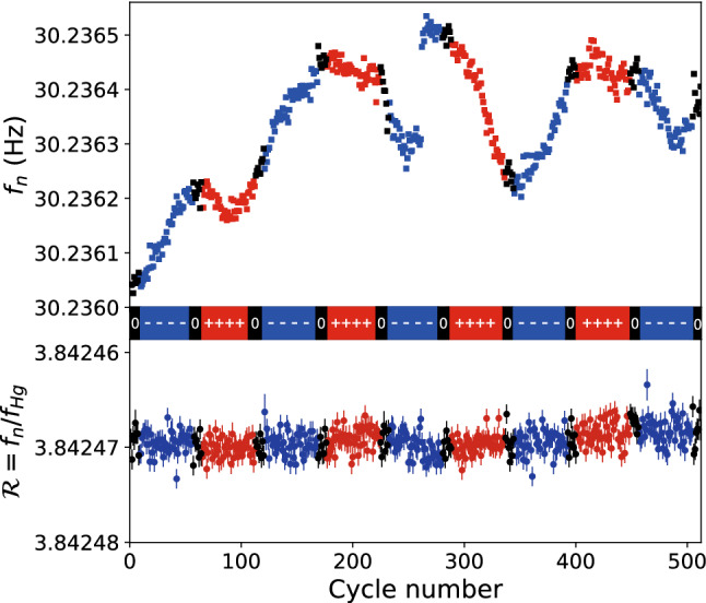
A sequence of nEDM data produced in 2016; each point corresponds to a single measurement cycle. The upper plot shows the neutron frequency as a function of cycle number, whereas the lower plot shows the frequency ratio . The colors correspond to the high-voltage polarity (blue, negative; red, positive; black, zero)

Simulated energy spectra of the detected UCNs. The energy is the sum of the kinetic and the gravitational potential energy calculated at the floor levels of the respective chambers

Storage curve measured with nEDM in 2017 (blue points) and simulated storage curve in n2EDM (black squares). The n2EDM storage curve is plotted as a function of the storage time t. It is fitted with a double exponential model as a function of the precession time , where is the number of neutrons at zero precession time and and are the fast and slow time constants

Projected daily sensitivity with n2EDM as a function of the precession time T. The baseline parameter is indicated by the black square

Measurement of the visibility after a precession time of as a function of an applied horizontal gradient performed with the nEDM apparatus in 2017. The dashed line corresponds to the exponential decay model , where is given by Eq. (18) with

Monte-Carlo simulation of the transverse field seen by a mercury atom in thermal ballistic motion inside one n2EDM precession chamber. Red lines with dots: motional field along y induced by the electric field. Blue line: non-uniform field along x in a (very large) gradient of

Longitudinal component of the phantom modes. Top: phantom mode of order 3 with . Bottom: phantom mode of order 5 with . Both field configurations generate a false EDM of . The light green rectangles represent the inner volume of the precession chambers

Magnetic dipole strength values corresponding to a residual systematic effect of (mean of top and bottom chambers), as a function of the position of the dipole in the plane. The direction of the dipole m was chosen to be along the z-axis, which is the most sensitive direction. This cut () intersects a unit of four magnetometers represented by the white circles. The top plate of the vacuum tank is represented by the horizontal black line at . The cross section of the electrodes are represented by the black and red-edged rectangles

False EDM due to a uniform field gradient (black), a 3-phantom mode (blue), a 5-phantom mode (red) as a function of the magnitude of the field for , ,

The full model of the n2EDM setup, displaying the core components of the experiment
Central part of the apparatus. Precession volumes are confined by HV and ground electrodes separated by insulator rings. The UCNs enter the chambers via UCN shutters

COMSOL simulation of the n2EDM optimised geometry. The central (high voltage) electrode is at a potential of 180 kV. The simulation is symmetric on the top and bottom half of the figure

Scheme of the beamline outside the MSR. The switch with movable UCN guides can operate in three modes: when UCNs are filling the precession chambers (filling configuration); when UCNs from the precession chambers are directed towards the two simultaneous spin-sensitive detectors (counting configuration); and a third (test) mode of the switch (not shown here) that permits guiding of UCNs directly from the source to the detectors in order to monitor the UCN source performance

Simultaneous spin analyzer. Each arm is equipped with an adiabatic spin-flipper (RF coil), a spin-analyzing foil and a UCN counter

Magnetic shielding. Passive shielding is provided by a large cubic magnetically shielded room (MSR). Active shielding consists of actively-controlled coils mounted on a grid around the MSR

Photo of the magnetically shielded room with indicated outer dimensions

The coil system inside the MSR (close to the innermost layer of the shield). For clarity, only the G10 coil is shown as an example of a gradient coil

COMSOL B-field simulation, showing field variations produced by the coil in the horizontal plane at m (left) and the vertical plane m (right). The rainbow scale corresponds to . The contours of the precession chambers, which have a diameter of 80 cm, are shown in white, while the innermost layer of the MSR is shown in blue on the edges of the plots. The black bold contour lines highlight B = 10, 100, and 1000 pT. The simulations are performed with the dimensions of the innermost layer of the MSR measured in situ. The values for the mu-metal material were communicated by the producer VAC and are proprietary information
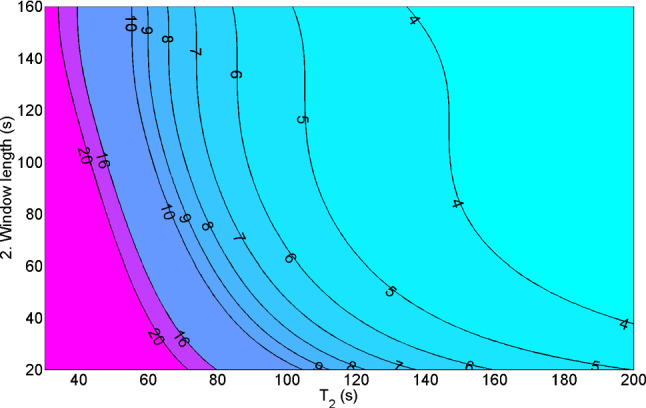
Statistical magnetometer uncertainty based on a signal/noise measurement using laser light to polarize and probe the Hg atoms. The values are given in fT as a function of the Hg spin depolarization time () and the length of the signal windows used for the analysis

Uncertainty of the calculation of the phantom gradient . The different curves show simulations for different assumptions of Cs magnetometer accuracy

Cutaway view of the mapper installed inside the vacuum vessel. The fluxgate can move along the , , and z axes and can explore almost the entire volume of the vacuum vessel
References
-
- M. Pospelov, A. Ritz, Ann. Phys. 318(1), 119 (2005). http://www.sciencedirect.com/science/article/pii/S0003491605000539
-
- J. Engel, M.J. Ramsey-Musolf, U. van Kolck, Prog. Part. Nucl. Phys. 71, 21 (2013). http://www.sciencedirect.com/science/article/pii/S0146641013000227
-
- Morrissey DE, Ramsey-Musolf MJ. New J. Phys. 2012;14(12):125003. doi: 10.1088/1367-2630/14/12/125003. - DOI
LinkOut - more resources
Full Text Sources