. 2021 Oct 26;31(44):2009289.
doi: 10.1002/adfm.202009289. Epub 2021 Feb 4.

Powering Implantable and Ingestible Electronics

Affiliations

Powering Implantable and Ingestible Electronics

So-Yoon Yang et al. Adv Funct Mater. .

Abstract

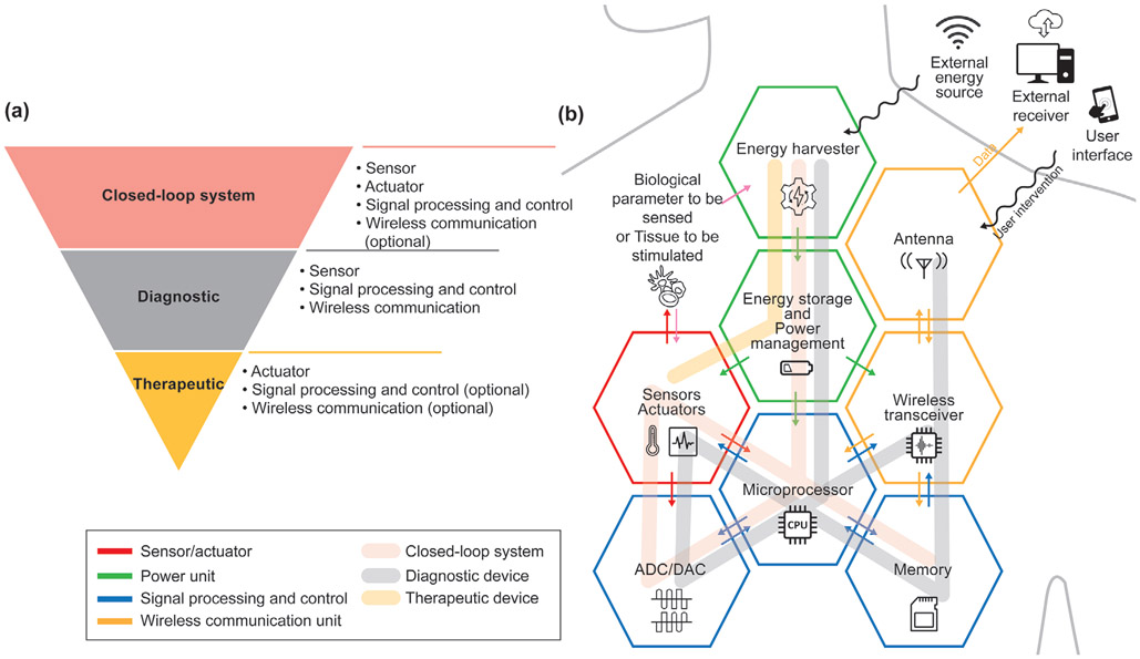
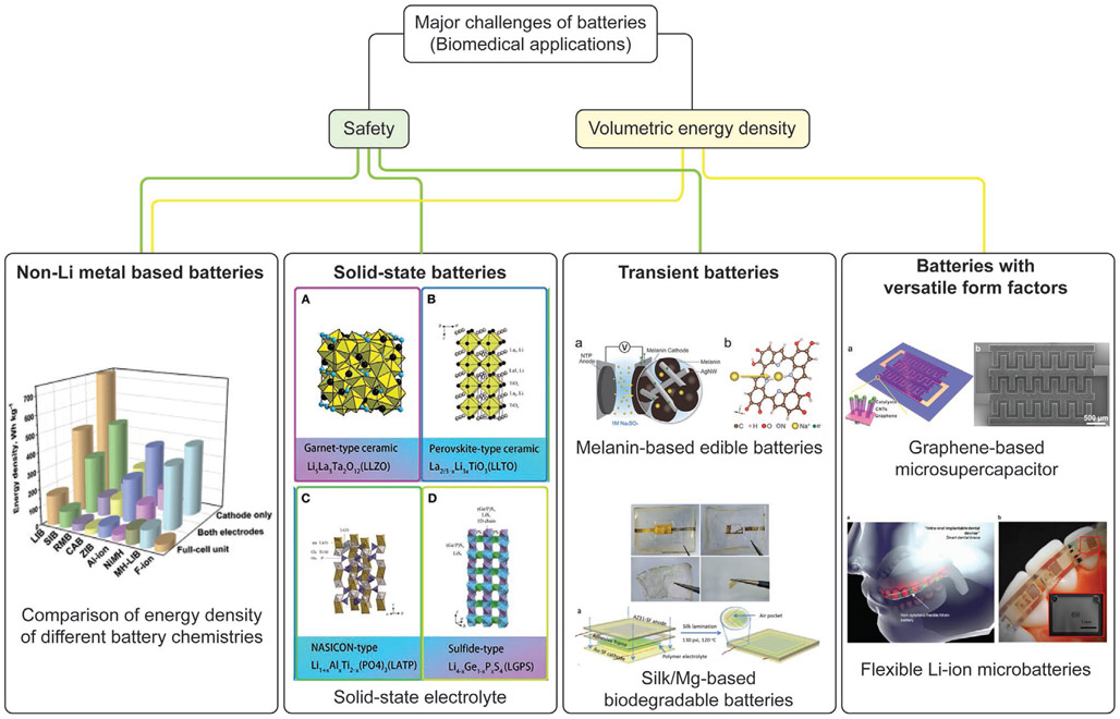
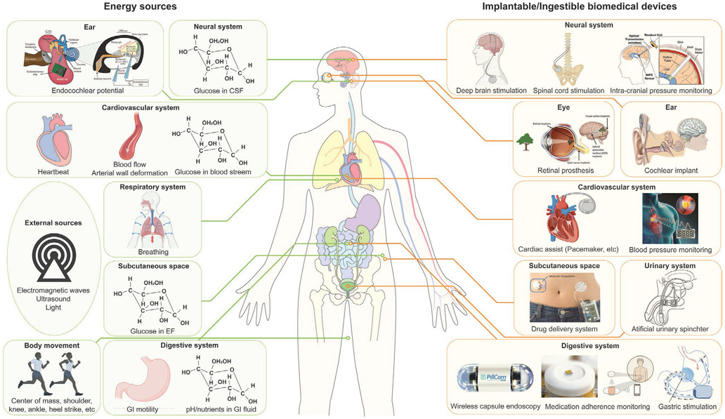
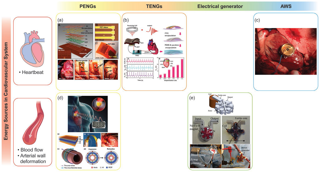
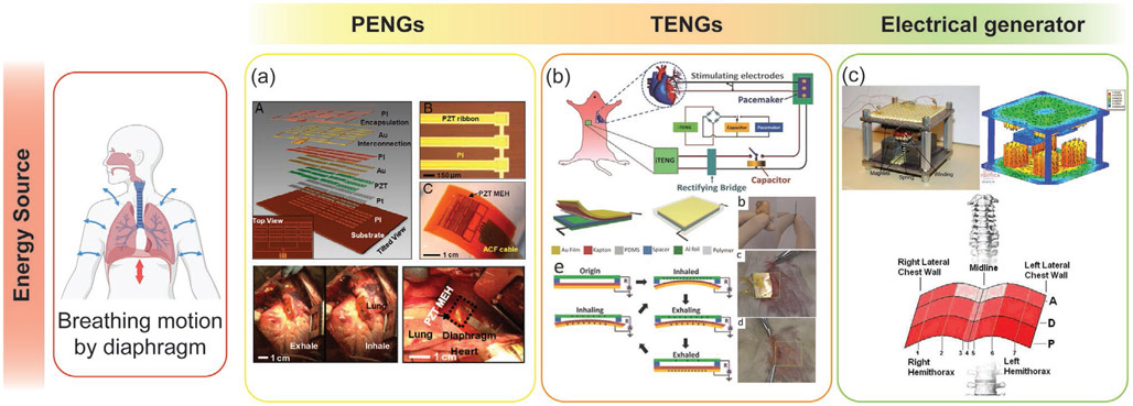
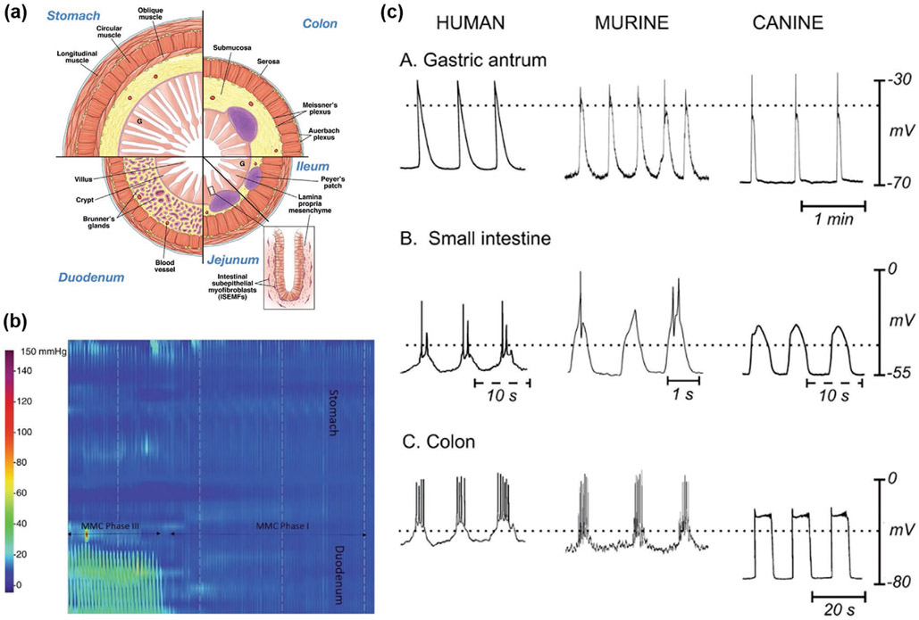
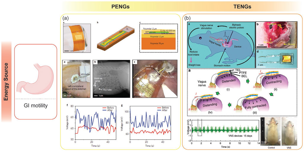
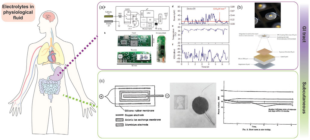
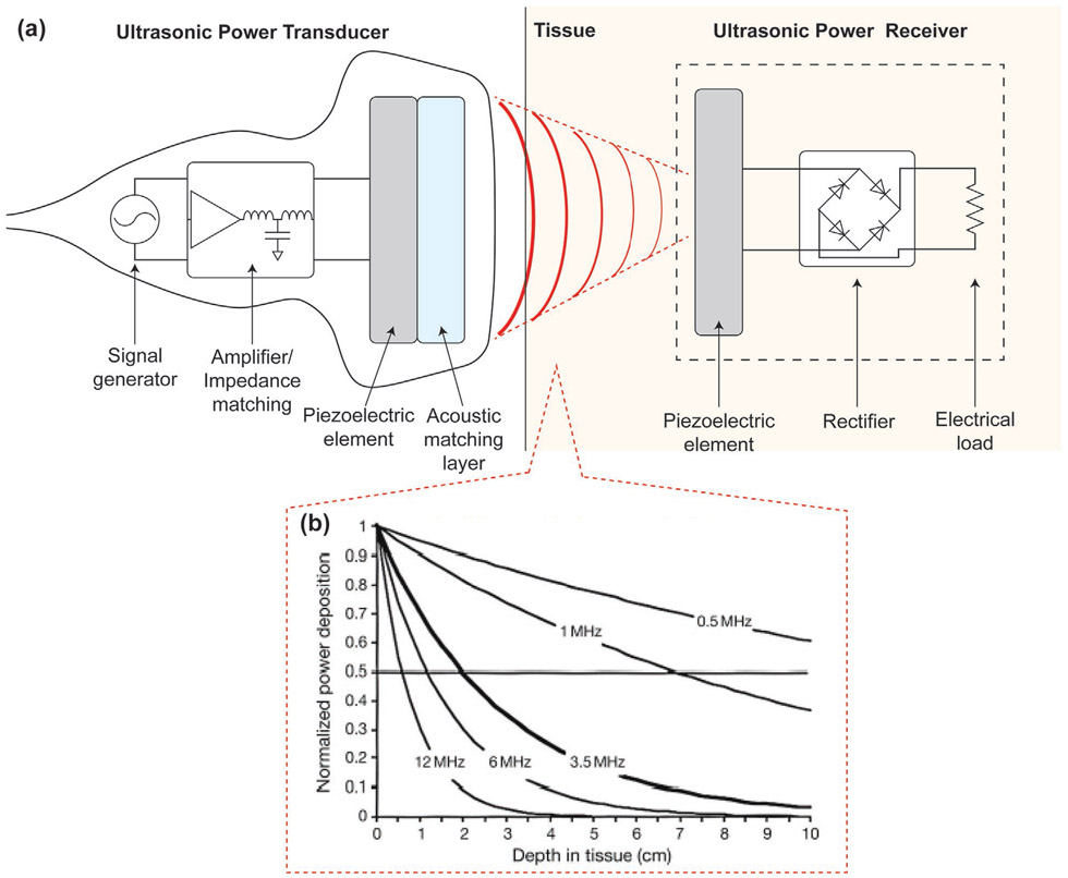
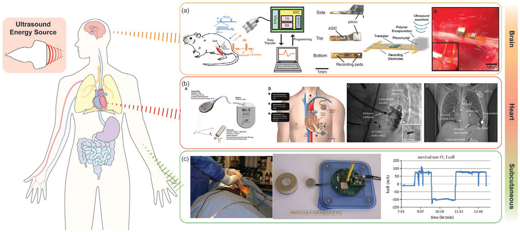
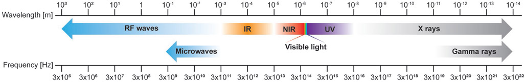
Implantable and ingestible biomedical electronic devices can be useful tools for detecting physiological and pathophysiological signals, and providing treatments that cannot be done externally. However, one major challenge in the development of these devices is the limited lifetime of their power sources. The state-of-the-art of powering technologies for implantable and ingestible electronics is reviewed here. The structure and power requirements of implantable and ingestible biomedical electronics are described to guide the development of powering technologies. These powering technologies include novel batteries that can be used as both power sources and for energy storage, devices that can harvest energy from the human body, and devices that can receive and operate with energy transferred from exogenous sources. Furthermore, potential sources of mechanical, chemical, and electromagnetic energy present around common target locations of implantable and ingestible electronics are thoroughly analyzed; energy harvesting and transfer methods befitting each energy source are also discussed. Developing power sources that are safe, compact, and have high volumetric energy densities is essential for realizing long-term in-body biomedical electronics and for enabling a new era of personalized healthcare.

Keywords: batteries; energy harvesting; energy transfer; implantable electronics; ingestible electronics.


Conflict of interest statement

Conflict of Interest G. T. is a co-inventor on multiple patent applications involving energy harvesting systems as well as systems involving electronics for therapeutic applications. G.T. reports receiving consulting fees from Novo Nordisk, Verily, Merck. G.T. has a financial interest in Lyndra Therapeutics, Suono Bio and Celero Systems which are all biotechnology companies developing therapeutics via the gastrointestinal tract which can include electronics in some embodiments. Complete details of all relationships for profit and not for profit for G.T. can found at the following link: https://www.dropbox.com/sh/szi7vnr4a2ajb56/AABs5N5i0q9AfT1IqIJAE-T5a?dl=0.

Figures

Figure 1.
Figure 1.
Timeline of major milestones for implantable and ingestible electronic devices and technology for powering such devices. Listed are the years when batteries suitable to power biomedical devices were first commercialized,[63-69] in vivo experiments of energy harvesting and transfer devices first occurred,[70-78] ingestible electronics first appeared,[79,80] and implantable electronics first appeared.[81-89] (WPT: wireless power transfer, BFC: biofuel cell, PENG: piezoelectric nanogenerator, APT: acoustic power transfer, AWS: automatic wristwatch system, PV: photovoltaic, TENG: triboelectric nanogenerator).
Figure 2.
Figure 2.
a) The system configuration and b) the schematic of functional units of closed-loop, diagnostic, and therapeutic implantable/ingestible electronics.
Figure 3.
Figure 3.
Current challenges of developing batteries for implantable/ingestible biomedical electronic devices and corresponding examples of technologies that address these issues. Reproduced with permission.[140] Copyright 2020, Elsevier. Reproduced with permission.[219] Copyright 2019, Frontiers Media S.A. Reproduced with permission.[220] Copyright 2016, Wiley-VCH. Reproduced with permission.[221] Copyright 2017, American Chemical Society. Adapted with permission.[222] Copyright 2017, American Chemical Society. Reproduced with permission[213] Copyright 2017, Springer Nature.
Figure 4.
Figure 4.
Energy sources available around the human body and biomedical devices that can be powered by these energy sources. Reproduced with permission.[223] Copyright 2012, Springer Nature. Adapted with permission.[224] Copyright 2011, IEEE. Reproduced with permission.[225] Copyright 2020, Elsevier. Reproduced with permission.[226] Copyright 2013, Elsevier. Reproduced with permission.[227] Copyright 2016, Elsevier. Adapted with permission.[228] Copyright 2010, SAGE Publications. Reproduced with permission.[229] Copyright 1996, Elsevier. Adapted with permission.[80] Copyright 2018, Springer Nature. Adapted with permission.[9] Copyright 2015, Springer Nature. Created with BioRender.com.
Figure 5.
Figure 5.
The working principle and operation modes of the PENGs. a) Electrical poling direction and preferential chain direction of the piezoelectric materials. For instance, in poly(vinylidene fluoride) (PVDF), the polar axis (labeled as direction “3”) is the direction of the applied electrical poling field. The polymer stretch direction or the preferential direction of the aligned polymer chains is denominated as direction “1” and is perpendicular to the polar axis. the axis orthogonal to the stretch direction “1” is labeled as “2.” The shear planes of piezoelectricity are indicated by the directions “4,” “5,” “6,” and are perpendicular to the directions to “1,” “2,” “3,” respectively.[238] The direction of the applied mechanical stress relative to the polar axis largely affects the performance of the piezoelectric energy harvesting device. b) The schematics of direct and converse piezoelectric effects. The direct piezoelectric effect appears when a mechanical stress is applied to a material, and the electric charges are generated proportional to the applied mechanical stress. Before the external stress is applied, the centers of the positive and negative charges of each molecule coincide and the material is in a neutral net electrical polarization. When a mechanical stress is applied and deforms the structure of the material, the positive and negative charges inside of the molecule will be separated and this leads to the generation of dipolar moments. When a mechanical stress is reversed, the polarity of dipolar moments will be reversed. This polarization generates an electric voltage output, which is the transformation of the mechanical vibration applied to the material into useful electrical energy to power electronic devices. The converse piezoelectric effect occurs when the electric field is applied to the piezoelectric material. The external electric field will change the position of electrons and nuclei in each molecule and dipoles will be created. These dipoles will result in the polarization of the material and ultimately induce the deformation of the material. When the electrical field is removed or reversed, the electrons and nuclei will move back to their original position, and the material will return to their initial geometry.
Figure 6.
Figure 6.
a) The triboelectric series of the common triboelectric materials used for biomedical applications.[270-275] b-e) The working principle and operation modes of TENGs.
Figure 7.
Figure 7.
The working principle of electrical generators. The electrical generators can be categorized by the type of relative motion between the magnets and coils: a) Linear or b) rotation. c) Homopolar generator or Faraday disk.
Figure 8.
Figure 8.
The working principle of AWSs.
Figure 9.
Figure 9.
Examples of systems that harvest mechanical energy from the circulatory system. a) Adapted with permission.[301] Copyright 2014, National Academy of Science. b) Adapted with permission.[305] Copyright 2016, American Chemical Society. c) Reproduced with permission.[307] Copyright 2012, Springer Nature. d) Adapted with permission.[227] Copyright 2016, Elsevier. e) Adapted with permission.[309] Copyright 2016, IEEE.
Figure 10.
Figure 10.
Examples of systems that harvest mechanical energy from the respiratory system. a) Adapted with permission.[301] Copyright 2014, National Academy of Science. b) Adapted with permission.[77] Copyright 2014, Wiley-VCH. c) Adapted with permission.[292] Copyright 2011, IEEE.
Figure 11.
Figure 11.
Mechanical physiology of the GI tract. a) Cross-section of cells in the GI tract. Reproduced with permission.[317] Copyright 2009, Elsevier. b) Manometry example showing a migrating myoelectric complex (MMC). Reproduced with permission.[318] Copyright 2020, Springer Nature. c) Example waveforms of the slow waves that regulate mechanical contraction. Reproduced with permission.[319] Copyright 2006, Annual Reviews Inc.
Figure 12.
Figure 12.
Examples of devices that harvest mechanical energy from GI tract. a) Adapted with permission.[343] Copyright 2017, Springer Nature. b) Adapted with permission.[93] Copyright 2018, Springer Nature.
Figure 13.
Figure 13.
The working principle of galvanic cells. a) The electrons flow from the oxidation reaction of anode to the reduction reaction of H+ (acidic physiological fluid) or O2 (neutral physiological fluid) at the cathode. b) Standard reduction potential (E0) of typical redox reactions at the anode and cathode.[345]
Figure 14.
Figure 14.
The working principle of biofuel cells. a) Abiotic biofuel cell, b) enzymatic biofuel cell, and c) microbial fuel cell. The ion exchange membranes are often omitted for implantable and ingestible biofuel cells to simplify the cell structure.
Figure 15.
Figure 15.
Examples of devices (biofuel cells) that harvest chemical energy from glucose in a) cerebrospinal fluid (CSF), b) blood, c) interstitial fluid (IF), and d) e) gastrointestinal fluid (GIF). a) Adapted with permission.[371] Copyright 2013, Springer Nature. b) Adapted with permission.[366] Copyright 2013, Royal Society of Chemistry. c) Adapted with permission.[362] Copyright 2018, Elsevier. d) Adapted with permission.[387] Copyright 2018, Royal Society of Chemistry. e) Reproduced with permission.[388] Copyright 2013, Elsevier.
Figure 16.
Figure 16.
Intraluminal physicochemical composition of GI tract.
Figure 17.
Figure 17.
Examples of devices (galvanic cells) that harvest chemical energy from electrolytes in a,b) gastric fluid and c) interstitial fluid (IF). Adapted with permission.[78] Copyright 2017, Springer Nature. Adapted with permission.[35] Copyright 2015, IEEE. Reproduced with permission.[378] Copyright 1969, Springer Nature.
Figure 18.
Figure 18.
a) working mechanism of an APT. ultrasound, which carries acoustic power, are emniea trom an ultrasonic power transducer, propagate through tissue layers, and are received by an ultrasonic power receiver located inside the body. In an ultrasonic power transducer, a signal generator generates an AC electrical signal and the Amplifier/Impedance matching circuitry amplifies and filters the signal. This signal causes the piezoelectric element to vibrate, generating ultrasonic waves with desired frequencies and amplitudes. Ultrasound travels through acoustic matching layers, which provide smooth transition of the acoustic impedance from the acoustic source to the medium. Without the matching layers, ultrasound will experience a large change in acoustic impedances when it propagates from the piezoelectric element to the medium (human tissue layers); this will cause the ultrasound to attenuate or even reflect back to the interface between the acoustic source and the medium. Ultrasound attenuates as it propagates through the human tissue layers. The attenuation rate depends on the frequency of ultrasound. b) The normalized power of transferred acoustic waves is a function of the tissue depth and ultrasound frequency.[420] When ultrasound reaches the receiver in the body, it vibrates the piezoelectric element and generate an AC electrical signal. The rectifier converts the AC signal to a DC signal and this harvested electrical energy can drive the electrical load to perform the desired task. Reproduced with permission.[420] Copyright 2014, Elsevier.
Figure 19.
Figure 19.
Examples of devices that harvest mechanical energy from exogenous ultrasonic energy source. a) Adapted with permission.[442] Copyright 2016, Elsevier. b) Adapted with permission.[444] Copyright 2013, Oxford University Press. c) Reproduced with permission.[440] Copyright 2016, Elsevier.
Figure 20.
Figure 20.
Electromagnetic spectrum.
Figure 21.
Figure 21.
The working principle of WPT. a) Electromagnetic waves can be classified into near-field and far-field regions depending on the distance from the electromagnetic source. The area within λ/2π is called the reactive near-field region, λ/2π ~ λ is the radiative near-field region, λ ~ 2 λ is the transition region, and over 2 λ is the far-field region. b) The schematics of different WPT techniques: near-, mid-, and far-field WPT. Inductive coupling near-field WPT employs coils as antennas for a power transmitter and a receiver, and the power transfer happens through magnetic field coupling. Capacitive coupling near-field WPT employs a pair of electrodes as antennas, and the electric field coupled between the electrodes transfer the energy from one to the other. Mid- and far-field WPT uses antennas (e.g., monopole, dipole, loop antennas) that can emit and receive radiative electromagnetic field. c) The penetration depths of electromagnetic or RF waves with different frequencies are shown.[453] The level of attenuation of RF waves varies slightly depending on tissue types. Adapted with permission.[453] Copyright 2016, Society for reproduction and fertility.
Figure 22.
Figure 22.
Examples of electromagnetic energy harvesting devices: WPT. a) Near-field power transfer to brain implants. Adapted with permission.[470] Copyright 2015, IEEE. b) Near-field power transfer to the peripheral nerve prosthesis implanted in the subcutaneous region. Adapted with permission.[466] Copyright 2015, IEEE. c) Mid-field power transfer to heart and brain implants to power a pacemaker. Adapted with permission.[91] Copyright 2014, National Academy of Sciences. d) Mid-field power transfer to GI tract to power ingestible electronics. Adapted with permission.[459] Copyright 2017, Springer Nature. e) Far-field power transfer to ocular implants. Reproduced with permission.[106] Copyright 2011, IEEE.
Figure 23.
Figure 23.
The working principle of optical transfer. a) The energy band diagram of p–n junction. b) The typical structure of photovoltaic cell. c) Attenuation of the visible and NIR light in different tissues. Reproduced with permission.[487] Copyright 2016, Springer Nature.
Figure 24.
Figure 24.
Examples of electromagnetic energy harvesting devices for optical transfer. a) Silicon-based PV cells implanted in subretinal region which harvest energy from NIR light. Adapted with permission. [474] Copyright 2015, Springer Nature. b) GaInP/GaAs-based flexible PV arrays implanted in the subcutaneous region which harvest energy from sunlight. Adapted with permission.[489] Copyright 2016, Wiley-VCH.

References

    1. Oeppen J, Vaupel JW, Science 2002, 296, 1029. - PubMed
    1. Brown GC, EMBO Rep. 2015, 16, 137. - PMC - PubMed
    1. Chronic Diseases in America ∣ CDC, 2020.
    1. LeRoy L, Bayliss E, Domino M, Miller BF, Rust G, Gerteis J, Miller T, A. M. R. Network, Med. Care 2014, 52, S15. - PubMed
    1. CDC, Disability Impacts All of Us Infographic ∣ CDC, 2019.

LinkOut - more resources