. 2021 Nov 5;12(1):6422.
doi: 10.1038/s41467-021-26711-z.

Nanoscale neural network using non-linear spin-wave interference

Affiliations

Nanoscale neural network using non-linear spin-wave interference

Ádám Papp et al. Nat Commun. .

Abstract

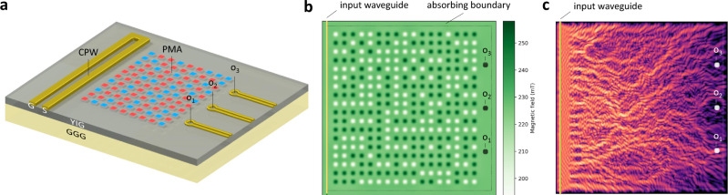
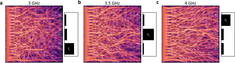
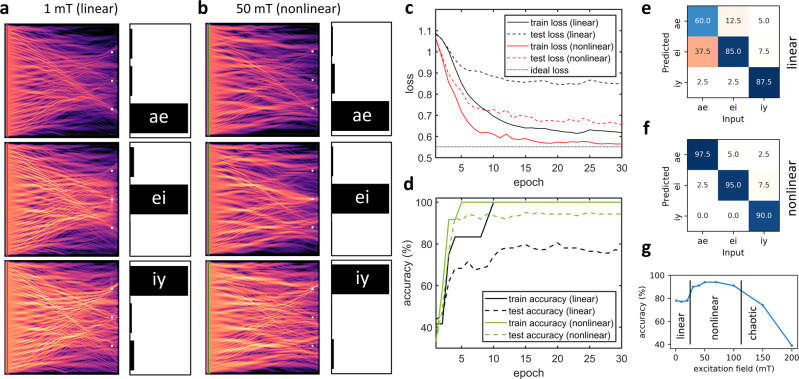
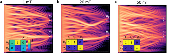
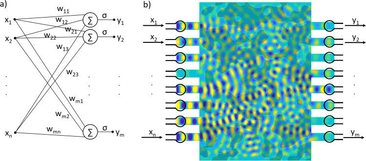
We demonstrate the design of a neural network hardware, where all neuromorphic computing functions, including signal routing and nonlinear activation are performed by spin-wave propagation and interference. Weights and interconnections of the network are realized by a magnetic-field pattern that is applied on the spin-wave propagating substrate and scatters the spin waves. The interference of the scattered waves creates a mapping between the wave sources and detectors. Training the neural network is equivalent to finding the field pattern that realizes the desired input-output mapping. A custom-built micromagnetic solver, based on the Pytorch machine learning framework, is used to inverse-design the scatterer. We show that the behavior of spin waves transitions from linear to nonlinear interference at high intensities and that its computational power greatly increases in the nonlinear regime. We envision small-scale, compact and low-power neural networks that perform their entire function in the spin-wave domain.


Conflict of interest statement

The authors declare no competing interests.

Figures

Fig. 1
Fig. 1. Nanomagnet-based spin-wave scatterer.
a The schematics of the envisioned computing device. The input signal is applied on the coplanar waveguide (CPW) on the left and the magnetic state (up/down) of programming magnets on top of the YIG film define the weights. b Magnets exhibiting perpendicular magnetic anisotropy are placed on top of the YIG film and generate a bias-field landscape. The training algorithm finds the binary state of the programming magnets. c Spin-wave intensity pattern for a particular applied input, which results in a high intensity at o1. The size of the simulation area is 10 μm × 10 μm.
Fig. 2
Fig. 2. Frequency separation by training.
ac The scatterer was trained to direct frequency components f1 = 3 GHz, f2 = 3.5 GHz, and f3 = 4 GHz to the corresponding outputs denoted by o1, o2, and o3. The bar charts indicate time-integrated intensities measured at the outputs (green circles). The colormaps show time-integrated intensity of spin waves at t = 30 ns. Black/white circles are contours of the out-of-plane component of the magnetic field, indicating the state of the magnets on top of the YIG film (same in all cases ac). The size of the simulation area is 10 μm × 10 μm.
Fig. 3
Fig. 3. Using the spin-wave scatterer for vowel recognition.
a, b Wave intensity patterns, formed in response to the time-domain excitations (vowels). The scatterer was trained to focus waves to the corresponding outputs. The bar charts show the intensity at the output locations (normalized). The linear regime a (1 mT excitation field) and the nonlinear regime b (50 mT excitation field) performs comparably well on the training data (slight improvement in case of nonlinear waves). c Cross-entropy loss decreases during the training, indicating learning. After 30 epochs (training steps), the nonlinear cases achieve better performance compared to the linear case. Note that a nonzero loss value corresponds to the perfect response, indicated by a dotted line. d Accuracy of vowel recognition on the training and testing data sets. e, f Confusion matrices over the testing data set (123 vowel samples). g Accuracy of vowel recognition (test set) as a function of excitation amplitude.
Fig. 4
Fig. 4. A simple example of a problem that is not solvable by a linear system.
Input is encoded in two frequencies (f1 = 3 GHz and f2 = 4 GHz) and the training function is listed in the inset tables (expected results indicated by numbers, output data are shown in color). a In the linear case (1 mT excitation field), application of simultaneous frequencies results in both o1 and o2 high (incorrect training). b, c In the nonlinear cases, the wave is focused at o2, but o1 is avoided (correct operation). In case of 50 mT excitation, the distinction is even stronger. The colormap shows integrated wave intensity. The size of the simulation area is 10 μm × 10 μm.
Fig. 5
Fig. 5. Understanding the spin-wave scatterer as a neural network.
a Is a schematic of an n-input, m-output perceptron layer (b) is an n-input, m-output spin-wave scatterer.

References

    1. Markovic, D., Mizrahi, A., Querlioz, D., & Grollier, J. Physics for neuromorphic computing. Nat. Rev. Phys. 2, 499–510 (2020).
    1. Hughes TW, Williamson IA, Minkov M, Fan S. Wave physics as an analog recurrent neural network. Sci. Adv. 2019;5:eaay6946. doi: 10.1126/sciadv.aay6946. - DOI - PMC - PubMed
    1. Chumak, A. V. in Spintronics Handbook: Spin Transport and Magnetism 2nd edn, 247–302 (CRC, 2019).
    1. Maendl S, Stasinopoulos I, Grundler D. Spin waves with large decay length and few 100 nm wavelengths in thin yttrium iron garnet grown at the wafer scale. Appl. Phys. Lett. 2017;111:012403. doi: 10.1063/1.4991520. - DOI
    1. Csaba G, Papp A, Porod W. Perspectives of using spin waves for computing and signal processing. Phys. Lett. A. 2017;381:1471–1476. doi: 10.1016/j.physleta.2017.02.042. - DOI