Review
. 2021 Oct 21:12:100152.
doi: 10.1016/j.mtbio.2021.100152. eCollection 2021 Sep.

Modification of the surface nanotopography of implant devices: A translational perspective

Affiliations
Review

Modification of the surface nanotopography of implant devices: A translational perspective

K Harawaza et al. Mater Today Bio. .

Abstract

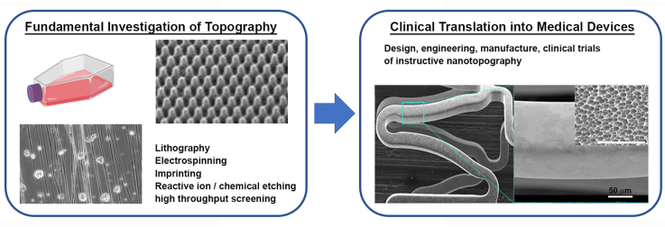
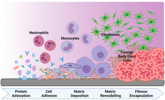
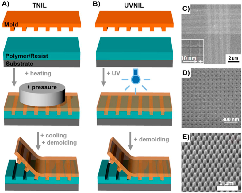
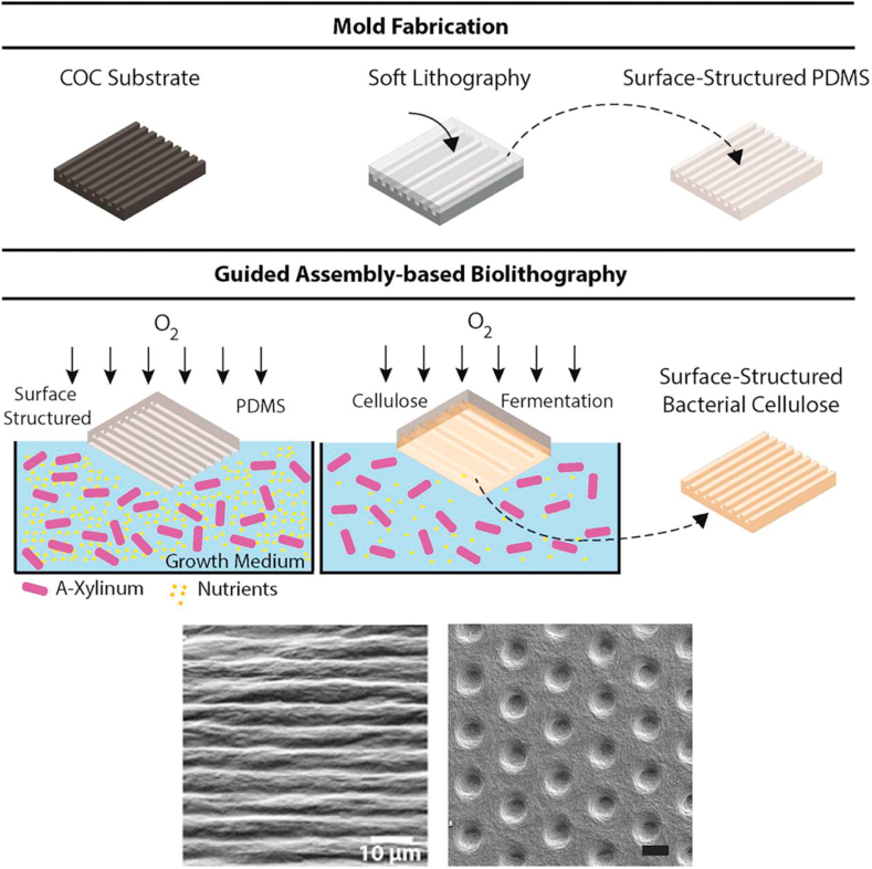
There is an increasing need for the development of superior, safe, and more sophisticated implants, especially as our society historically has been moving towards an increasingly aging population. Currently, most research is being focused on the next generation of advanced medical implants, that are not only biocompatible but have modified surfaces that direct specific immunomodulation at cellular level. While there is a plethora of information on cell-surface interaction and how surfaces can be nanofabricated at research level, less is known about how the academic knowledge has been translated into clinical trials and commercial technologies. In this review, we provide a clinical translational perspective on the use of controlled physical surface modification of medical implants, presenting an analysis of data acquired from clinical trials and commercial products. We also evaluate the state-of-the-art of nanofabrication techniques that are being applied for implant surface modification at a clinical level. Finally, we identify some current challenges in the field, including the need of more advanced nanopatterning techniques, the comparatively small number of clinical trials and comment on future avenues to be explored for a successful clinical translation.

Keywords: Clinical translation; Clinical trials; Implants; Nanotopography; Surface modification.


Conflict of interest statement

The authors declare that they have no known competing financial interests or personal relationships that could have appeared to influence the work reported in this paper.

Figures

Image 1
Graphical abstract
Fig. 1
Fig. 1
Response to implant. Temporal representation of the events following medical device implantation, including a selection of the cell types and the complexity of the interactions/matrix composition occurring over time (left to right).
Fig. 2
Fig. 2
Schematic illustration of NIL process. A) Thermal heating (TNIL) uses heating and pressure for hardening and pattern transfer and B) Ultraviolet (UVNIL) uses UV light. C-E) Scanning electron microscopy images of nanotopographies of various shapes and sizes, that were successfully transferred to different substrates using NIL. Images modified from [60] under Creative Commons license.
Fig. 3
Fig. 3
Schematic illustration of GAB nanofabrication process. Top: fabrication of PDMS mould using a template. Centre: the PDMS mould previously fabricated is used to cultivate cellulose as the bacterial growth media, thus allowing a patch of cellulose to develop on the top [64]. Copyright 2015, ACS. Bottom: Examples of nanopatterns that can be fabricated using GAB. Scale bars represent 10 ​μm [[64], [65]]. Copyright 2015, ACS. Copyright 2018, Springer Nature, under a Creative Commons Attribution 4.0 International.
Fig. 4
Fig. 4
Schematic illustrations of GCIB and Electrospinning processes. A) GCIB process and B) example of the type of patterns that can be obtained on metal surfaces (Au) after GCIB process [70]. Copyright 2001, Elsevier. C) Nanofiber formation during the electrospinning process and D) scanning electron microscopy images of fibers with different orientation that can be obtained using electrospinning. Figure modified from [74] Copyright 2019, Springer One, under a Creative Commons Attribution 4.0 International.
Fig. 5
Fig. 5
IMP and Nanotopochip platforms. (A) IMP fabrication process showing bonded plates assembly. The PDMS thickness is controlled by changing the relative thickness of Si wafer and the shims in four corners. (B) The patterned areas are then bonded to a multi-well plate thermoplastic plate previously treated with O2 plasma. The bottom surface of the plate is composed of PDMS nanotopographies. (C) Final integrated mechanobiology platform, in a 96 well plate configuration, enabling high through-put cell response analysis [92]. Copyright 2016, ACS. (D) TopoWellPlate is part of the TopoChip platform: Collectives of primitive shapes are used to design topographical features. Arrays of a unique topographical feature built in a 290 ​× ​290 ​μm TopoUnits, giving a total of 2176 TopoUnits with unique topographies and 4 unpatterned units for each Topochip. TopoWellPlate contains 87 unique surface topographies and 9 unpatterned wells incorporated by thermal bonding [93b]. Copyright 2017, John Wiley and Sons Inc.
Fig. 6
Fig. 6
A) Scanning electron microscopy images of implanted micro-structured pouch fabricated using CellSense technology: Left: Image showing the fibrous structure (scale bar 2 ​μm) Right: Micro-well pattern on BC surface. Top-right inset detail of the micro-wells, where the fibrous structure of the material is evident. Bottom-left inset top-view schematic of the layout of the micro wells on the surface. Right inset: Red circles represent the micro-wells, solid black line depicts the hexagonal arrangement of the features and the blue dashed line highlights the elemental cell shaped as an equilateral triangle with 10 ​μm side length. Scale bar 300 ​μm. Scale bar in the inset 5 ​μm. B) Process chart of the surgical intervention during the in vivo implantation of the seamless pouch [102]. Copyright 2020, Science Direct. Ci) Scanning electron microscopy image of Nano+™ polymer-free stent nanotopography. Cii and inset) showing the size of the nano pores at a magnification of×20,000 and ​× ​6000 (inset). Figure modified from [105]. Copyright 2020, John Wiley and Sons Inc. (For interpretation of the references to colour in this figure legend, the reader is referred to the Web version of this article.)
Fig. 7
Fig. 7
Ti-PEEK spinal implants with hierarchical roughness. A) Pictures of implanted samples used to study the influence of hierarchical roughness with calcium deposition compared to other surfaces and B) Graph showing in vitro variations in the calcium deposition comparing the 3 implanted surfaces, showing the Ti-PEEK implant (TyPEEK, Tyber Medical) with the highest increased calcium deposition in presence of human osteoprogenitor cells [117]. Copyright 2019, Science Direct, under a Creative Commons Attribution 4.0 International. C) Right: SEM image of micro and nanoscale topography achieved using SLA on coated titanium plasma-sprayed PEEK for spinal implants. The hierarchical structure is composed by cavities with diameters of wider indentations of about 10–50 ​μm completely superposed by smaller pores of about 1–2 ​μm diameter. Left: profilometric contact style topography representing the surface waviness. Figure modified from [116]. Copyright 2005, John Wiley and Sons Inc.
Fig. 8
Fig. 8
Ti-Coated PEEK spinal implants. A) SEM images of spinal implant (nano FortiCore®, Nanovis) coated with TiO2 nanotubes with different pore diameters: i) 30 ​nm, ii) 70 ​nm, iii) 100 ​nm. B, C, D, E) Fluorochrome images of surrounding tissue of spinal implants showing new bone formation around all implants modified by (B) machined implant, (C) coated with 30 ​nm TiO2 nanotubes, (D) 70 ​nm TiO2 nanotubes and (e) 100 ​nm TiO2 nanotubes, with different markers: xylene orange-labeled lines (orange), calcein-labeled lines (green), alizarin-labeled lines (red). Figure modified from [118]. Copyright 2011, ScienceDirect. (For interpretation of the references to colour in this figure legend, the reader is referred to the Web version of this article.)

References

    1. IMAP Insights Report . IMAP Inc; Barcelona, Spain: 2020. The Global Medical Device Market.
    1. Crawford R., Murray D. Total hip replacement: indications for surgery and risk factors for failure. Ann. Rheum. Dis. 1997;56 doi: 10.1136/ard.56.8.455. 455–45. - DOI - PMC - PubMed
    1. Zupnik J., Kim S., Ravens D., Karimbux N., Guze K. Factors associated with dental implant survival: a 4-year retrospective analysis. J. of Periodotol. 2011;82:1390–1395. doi: 10.1902/jop.2011.100685. - DOI - PubMed
    1. Arciola C.R., Campoccia D., Montanaro L. Implant infections: adhesion, biofilm formation and immune evasion. Nat. Rev. Microbiol. 2018;16:397–409. doi: 10.1038/s41579-018-0019-y. - DOI - PubMed
    2. Wodajo F.M., Jakus A.E. Nanopatterning and bioprinting in orthopedic surgery. Orthop. Clin. N. Am. 2019;50:21–33. doi: 10.1016/j.ocl.2018.08.013. - DOI - PubMed
    1. Ben-Menahem S.M., Nistor-Gallo R., Macia G., von Krogh G., Goldhahn J. How the new European regulation on medical devices will affect innovation. Nat. Biomed. Eng. 2020;4:585–590. doi: 10.1038/s41551-020-0541-x. - DOI - PubMed

LinkOut - more resources