. 2021 Nov 19;10(11):3105-3116.
doi: 10.1021/acssynbio.1c00371. Epub 2021 Nov 11.

A Microfluidic Platform for Sequential Assembly and Separation of Synthetic Cell Models

Affiliations

A Microfluidic Platform for Sequential Assembly and Separation of Synthetic Cell Models

Ran Tivony et al. ACS Synth Biol. .

Abstract

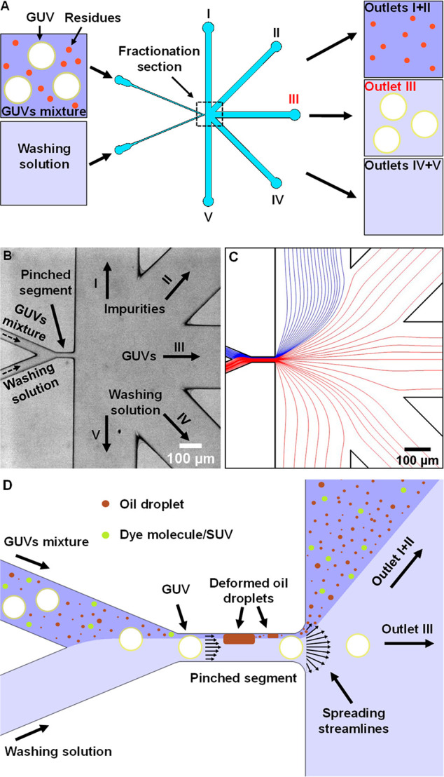
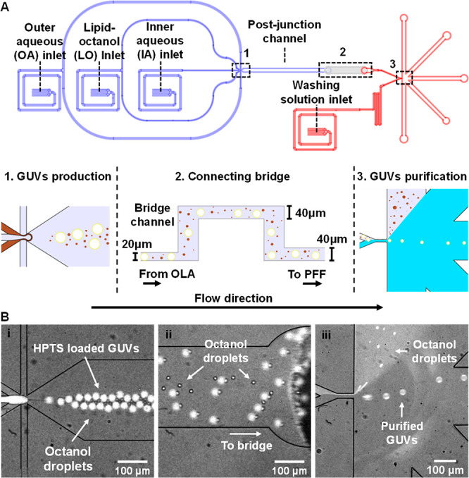
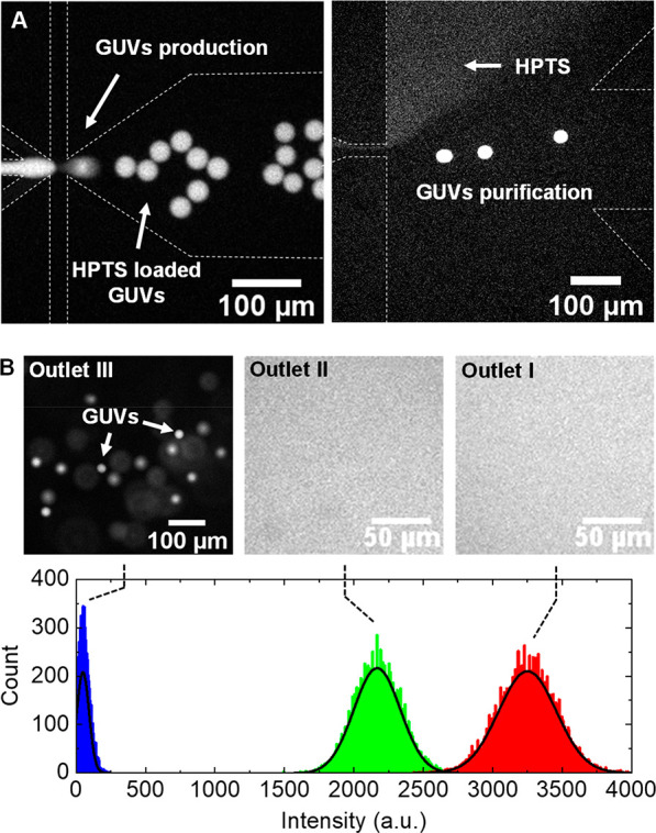
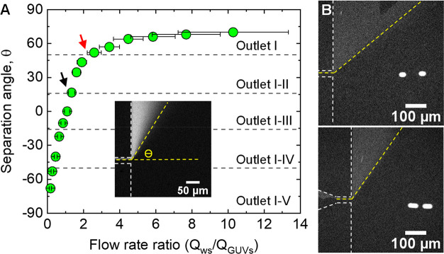
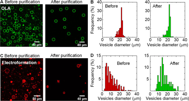
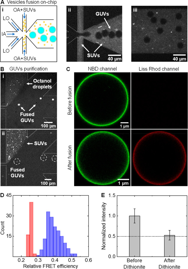
Cell-sized vesicles like giant unilamellar vesicles (GUVs) are established as a promising biomimetic model for studying cellular phenomena in isolation. However, the presence of residual components and byproducts, generated during vesicles preparation and manipulation, severely limits the utility of GUVs in applications like synthetic cells. Therefore, with the rapidly growing field of synthetic biology, there is an emergent demand for techniques that can continuously purify cell-like vesicles from diverse residues, while GUVs are being simultaneously synthesized and manipulated. We have developed a microfluidic platform capable of purifying GUVs through stream bifurcation, where a vesicles suspension is partitioned into three fractions: purified GUVs, residual components, and a washing solution. Using our purification approach, we show that giant vesicles can be separated from various residues─which range in size and chemical composition─with a very high efficiency (e = 0.99), based on size and deformability of the filtered objects. In addition, by incorporating the purification module with a microfluidic-based GUV-formation method, octanol-assisted liposome assembly (OLA), we established an integrated production-purification microfluidic unit that sequentially produces, manipulates, and purifies GUVs. We demonstrate the applicability of the integrated device to synthetic biology through sequentially fusing SUVs with freshly prepared GUVs and separating the fused GUVs from extraneous SUVs and oil droplets at the same time.

Keywords: artificial cell models; bottom-up synthesis; giant unilamellar vesicles; giant vesicle purification; lipid bilayer; microfluidics.


Conflict of interest statement

The authors declare no competing financial interest.

Figures

Figure 1
Figure 1
Design and basic principle of giant unilamellar vesicle (GUV) purification on-chip (A) Schematic illustration of continuous purification of GUVs based on pinched flow fractionation (the actual design is depicted in Figure S1). An isosmotic washing solution and a mixture of GUVs are perfused through the chip inlets to a fractionation section which splits them to different branch channels and outlets: impurities flow to outlets I and II; GUVs in washing solution flow to outlet III; and washing solution flows to outlets IV and V. (B) A micrograph of the microfluidic fractionation section (marked with a dotted line square in A) with the relevant components shown in the figure, illustrating the separation concept of the purification module. (C) Simulation of the fluid streamlines, with the relevant components depicted in the panel, showing the concept of stream bifurcation—a blue stream (i.e., GUVs mixture) is focused on the pinched segment sidewall by a red stream (i.e., washing solution). (D) Illustration of the main concept of vesicles purification using a narrow pinched-segment with a width comparable to the diameter of GUVs. As the GUVs mixture is forced to the pinched segment sidewall by the washing solution stream, the vesicles mixture, along with all components (i.e., impurities), is separated by the spreading streamlines from vesicles whose center of mass is positioned at the microchannel centerline. In the case of large oil droplets (i.e., when wa; see main text), the viscous force inside the pinched segment stretches the oil droplets so their center of mass is shifted away from the microchannel centerline and toward its sidewall. On the other hand, the GUVs membrane is practically inextensible (hence, their surface area and volume are constant) so their center of mass is kept at (or close) the centerline.
Figure 2
Figure 2
Continuous purification of GUVs using an integrated device that combines vesicle production and purification. (A) CAD design of the integrated microfluidic device (using AutoCAD), with its principal components labeled, showing the incorporation of a GUV production module (blue; design thickness, 20 μm) with the purification module (red; design thickness, 40 μm), using a connecting bridge channel (light gray; design thickness, 40 μm) through which the GUVs mixture flow from one unit to the other. The integrated device has 4 perfusion inlets (three for OLA—IA, LO, and OA—and one for the washing solution) and 5 outlets. (B) Fluorescent micrographs showing the sequential production and continuous purification of GUVs (labeled with HPTS (lumen) and Liss Rhod PE (membrane)) on the integrated chip. The formed HPTS-loaded GUVs (i) are drifting to the connecting bridge channel through the OLA postjunction channel outlet (ii) and reaching the purification unit where they are separated from octanol droplets using a focusing stream of a washing solution (iii). For clarity, panels (i) and (ii) show the formation and drift of vesicles in the HPTS fluorescent channel, and panel (iii) illustrates the separation of these freshly formed vesicles from oil droplets in the Lissamine Rhodamine fluorescent channel (Liss Rhod PE is in the octanol phase and in the GUVs membrane).
Figure 3
Figure 3
Purification efficiency and vesicles recovery. (A) Fluorescent micrographs depicting the sequential production (left image) and purification of HPTS-loaded GUVs from free HPTS (right image) on an integrated device. (B) The upper panel shows fluorescent micrographs of the fraction collected from each outlet (I, II, and III). The bottom panel indicates the pixel count for the fluorescence intensity in each outlet, where the black solid lines are the best fit of a Gaussian distribution to the data. In outlet III, the fluorescence intensity was obtained by measuring the background signal, excluding focused and blurred (out-of-focus) GUVs, and for outlets I and II the intensity was measured over a similar pixel area as in outlet III.
Figure 4
Figure 4
(A) Measurements of separation angle θ as a function of flow rate ratio between the washing solution and GUVs mixture channels (Qws/QGUVs). The separation angle at different flow rate ratios was measured through focusing an HPTS solution using a second stream at variable flow velocities, as shown in the inset. The black and red arrows indicate the flow rate ratios at which the HPTS solution is bifurcated to outlet I and II and outlet I, respectively. (B) Purification of GUVs at flow rate ratios of ∼1.6 (upper) and ∼2.6 (bottom), showing that the flow of GUVs to outlet III is not affected by the relative flow rate at the GUVs mixture and washing solution channels. The vesicles velocity u in each case, ∼0.0006 m s–1 (upper) and ∼0.001 m s–1 (bottom), was estimated from the figures using u = Δdt, where Δd is the vesicle displacement measured from the distance between the estimated centers of two circles (a = 23.3 μm) that compose the blurred vesicle and Δt is the camera exposure time which, in our setup, is inversely proportional to the frame rate (Δt = 1/FPS = 0.025 s).
Figure 5
Figure 5
Separation of OLA-GUVs and electroformed-GUVs. (A) Confocal images of OLA-GUVs before and after separation from octanol droplets. (B) Frequency histogram of vesicle size distribution before (n = 168) and after (n = 107) purification. (C) Confocal images of electroformed giant vesicles before and after purification showing the successful recovery of GUVs and exclusion of lipid aggregates. The washing solution was the same solution in which vesicles were prepared (Experimental Section). (D) Frequency histogram vesicle size distribution before (n = 337) and after (n = 105) purification demonstrating the exclusion of giant vesicles with diameters a < 7 μm. Assuming a Gaussian distribution the average diameter of filtered vesicles is = 15 ± 9 μm.
Figure 6
Figure 6
Charge-mediated vesicles fusion using the integrated production-purification microfluidic device. (A) (i) A schematic showing the concept of on-chip fusion between positively charged SUVs and freshly prepared negatively charged GUVs. (ii) A fluorescent image showing the production and fusion of DOPE-NBD labeled GUVs with DOPE-Rh labeled SUVs. SUVs are perfused through the outer aqueous channel. (iii) A fluorescent image showing the mixing of SUVs and GUVs in the postjunction channel. Both images (ii) and (iii) were acquired at an excitation wavelength of 550 nm to visualize the SUVs and the white dashed lines were added to illustrate the microchannels contour. (B) Simultaneous separation of fused GUVs from octanol droplets and SUVs (R = 65 nm; zeta potential ζ = +44 mV) using the purification unit of the integrated device (Figure S1). (C) Confocal images (a magnified view) of GUVs, settled at the bottom of the imaging chamber, before (upper panel) and after (bottom panel) fusion with SUVs. The images were acquired at excitation wavelengths of 488 and 559 nm to illustrate the transfer of DOPE-Rh from SUVs to GUVs. (D) Relative FRET efficiency (EFRET = IRh/(IRh + INBD)) measurement before (red bars, n = 57) and after (blue bars, n = 192) fusion. The fluorescence intensity of Rh and NBD was measured after excitation of the latter at wavelength of 488 nm. (E) Examination of membrane unilamellarity following on-chip fusion of positively charged SUVs (labeled with DOPE-NBD) and negatively charged GUVs, using dithionite reduction of NBD-PE lipids (see main text). The averaged fluorescence intensity of the fused GUVs membrane was measured before (n = 28) and after 30 min (n = 24) from the addition of dithionite. Fluorescence intensity was normalized based on the fluorescence intensity before the addition of dithionite.

References

    1. Robinson T. Microfluidic handling and analysis of giant vesicles for use as artificial cells: a review. Advanced Biosystems 2019, 3, 1800318.10.1002/adbi.201800318. - DOI - PubMed
    1. Matosevic S. Synthesizing artificial cells from giant unilamellar vesicles: State-of-the art in the development of microfluidic technology. BioEssays 2012, 34, 992–1001. 10.1002/bies.201200105. - DOI - PubMed
    1. Göpfrich K.; Platzman I.; Spatz J. P. Mastering complexity: towards bottom-up construction of multifunctional eukaryotic synthetic cells. Trends Biotechnol. 2018, 36, 938–951. 10.1016/j.tibtech.2018.03.008. - DOI - PMC - PubMed
    1. Litschel T.; Schwille P. Protein Reconstitution Inside Giant Unilamellar Vesicles. Annu. Rev. Biophys. 2021, 50, 525.10.1146/annurev-biophys-100620-114132. - DOI - PubMed
    1. Walde P.; Cosentino K.; Engel H.; Stano P. Giant vesicles: preparations and applications. ChemBioChem 2010, 11, 848–865. 10.1002/cbic.201000010. - DOI - PubMed

Publication types

MeSH terms