. 2021 Oct 28;21(21):7178.
doi: 10.3390/s21217178.

Modeling Pulsed High-Power Spikes in Tunable HV Capacitive Drivers of Piezoelectric Wideband Transducers to Improve Dynamic Range and SNR for Ultrasonic Imaging and NDE

Affiliations

Modeling Pulsed High-Power Spikes in Tunable HV Capacitive Drivers of Piezoelectric Wideband Transducers to Improve Dynamic Range and SNR for Ultrasonic Imaging and NDE

Antonio Ramos et al. Sensors (Basel). .

Abstract

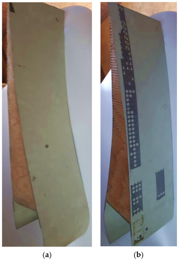
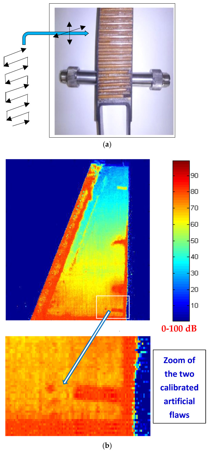
The signal-to-noise ratios (SNR) of ultrasonic imaging and non-destructive evaluation (NDE) applications can be greatly improved by driving each piezoelectric transducer (single or in array) with tuned HV capacitive-discharge drivers. These can deliver spikes with kW pulsed power at PRF ≈ 5000 spikes/s, achieving levels higher even than in CW high-power ultrasound: up to 5 kWpp. These conclusions are reached here by applying a new strategy proposed for the accurate modeling of own-design re-configurable HV capacitive drivers. To obtain such rigorous spike modeling, the real effects of very high levels of pulsed intensities (3-10 A) and voltages (300-700 V) were computed. Unexpected phenomena were found: intense brief pulses of driving power and probe emitted force, as well as nonlinearities in semiconductors, though their catalog data include only linear ranges. Fortunately, our piezoelectric and circuital devices working in such an intense regime have not shown serious heating problems, since the finally consumed "average" power is rather small. Intensity, power, and voltage, driving wideband transducers from our capacitive drivers, are researched here in order to drastically improve (∆ >> 40 dB) their ultrasonic "net dynamic range available" (NDRA), achieving emitted forces > 240 Newtonspp and receiving ultrasonic signals of up to 76-205 Vpp. These measurements of ultrasonic pulsed voltages, received in NDE and Imaging, are approximately 10,000 larger than those usual today. Thus, NDRA ranges were optimized for three laboratory capacitive drivers (with six commercial transducers), which were successfully applied in the aircraft industry for imaging landing flaps in Boeing wings, despite suffering acoustic losses > 120 dB.

Keywords: HV capacitive-discharge drivers; NDRA; efficient ultrasonic transceivers; high-current driving; industrial NDE; medical imaging; net dynamic range; pulsed high-power spikes; wideband piezoelectric transducers.


Conflict of interest statement

The authors declare no conflict of interest.

Figures

Figure 1
Figure 1
Structure of our HR ultrasonic imaging systems designed in CSIC, which contain a number of controlled E/R ultrasonic channels (from 16 to 128). It usually includes n analogic transceivers digitally controlled by complex systems for electronic focusing and HV scanning in emission and reception stages, and a unit for processing and displaying of the received signals and images.
Figure 2
Figure 2
Lab equipment of own design for capacitive multi-driving, electronic focusing, and HV scanning [15] of PZT transducers.
Figure 3
Figure 3
Block diagram of our HV pulsed driver for efficient excitation of broadband transducers.
Figure 4
Figure 4
Circuital schemes for the blocks involved in Figure 3: (a) capacitive ramp generator and (b) pulse shaper and selective damping.
Figure 5
Figure 5
Our own-design reconfigurable HV electronic transceiver (a) and wideband piezoelectric transducers (b) that have been employed in the experimental works shown and analyzed here.
Figure 6
Figure 6
Scheme of our global circuital modeling for emitter responses simulation under high-power capacitive driving in the high-frequency range, with electrical non-ideal behaviors and quadratic piezoelectric losses in XT.
Figure 7
Figure 7
Scheme of a practical option we propose for circuital modeling (in P-Spice) of ultrasonic transceivers under pulsed high-power capacitive driving, for intermediate frequency ranges: (a) HV capacitive driver, (b) piezoelectric subsystems with mechanical piezoelectric losses in E/R mode.
Figure 8
Figure 8
Measured HV spike waveform when driving a broadband piezoelectric transducer in the MHz range (Q269), showing mechanical influences from transducer vibrations during the first 4 µs.
Figure 9
Figure 9
(a) Computer simulation of the HV driver spike related to the measured HV waveform of Figure 8, also showing the motional effects from the driven transducer, superimposed on the spike. (b) Calculated transient motional force over the transducer radiating face, originating those effects.
Figure 10
Figure 10
(a). Measured frequency spectra of real (G) and imaginary (B) parts of the electrical admittance in the untuned Q269 broadband transducer. (b) Experimental basic frequency band of the received signal in a Q270 transducer, connected in a through-transmission scheme, without any inductive tuning in either stage, and when Q269 is driven by our HV capacitive driver.
Figure 11
Figure 11
Output current (a) and power (b) waveforms simulated for our tuned HV capacitive driver loaded with the Q269 transducer, using our circuital models of Figure 7. Resulting force (c) and velocity (d) pulses, calculated for the transducer face emitting on a methacrylate (PMMA) plastic medium.
Figure 12
Figure 12
Improvements in the ultrasonic signal measured in T–T mode through a PMMA piece, due to our tuned HV capacitive driver: (a) bandwidth; (b) time response (in dashed line, with tuning).
Figure 13
Figure 13
NDE test pieces (landing flap transversal portion, containing mainly air) of (a) Boeing-777 plane wings, fabricated for the maker (b) with internal artificial flaws located in unknown ubications.
Figure 14
Figure 14
Application of our tuned capacitive driver for NDE of a portion of landing flap in Boeing-777 wing. (a) Laboratory-scale mock-up showing how ultrasonic C-Scan imaging was made, with two T–T transducers (here, the real piece of Figure 13 and water jets are not shown). (b) The very sharp imaging that was achieved, overpassing losses (into the inspected flap and water jets) of up to 150 dB.
Figure 15
Figure 15
Our T–T received signals with both probes in direct contact: (a,b) KBA Delta Krautkrämer probes (5 V/div.). (c) L-N Tecal probes (50 V/div.). The driving was tuned in (b,c) responses. In all three cases: 1 μs/div. in horizontal axes.

References

    1. Thurston R.N. Effect of electrical and mechanical terminating resistances on loss and bandwidth according to the conventional equiva-lent circuit of a piezoelectric transducer. IRE Trans. Ultrason. Eng. 1960;UE-7:16–25. doi: 10.1109/T-PGUE.1960.29256. - DOI
    1. Kossoff G. The Effects of Backing and Matching on the Performance of Piezoelectric Ceramic Transducers. IEEE Trans. Sonics Ultrason. 1966;13:20–30. doi: 10.1109/T-SU.1966.29370. - DOI
    1. Filipczynski L. Transient equivalent circuit and negative capacitance of a piezoelectric transducer performing thickness vibrations. J. Tech. Phys. 1975;16:121–135.
    1. Hayward G. The influence of pulser parameters on the transmission response of piezoelectric transducers. Ultrasonics. 1985;23:103–112. doi: 10.1016/0041-624X(85)90058-7. - DOI
    1. Ramos A., Sanz P.T., Montero F.R. Broad-band driving of echographic arrays using 10 ns-500 V efficient pulse generators. Ultrasonics. 1987;25:221–228. doi: 10.1016/0041-624X(87)90037-0. - DOI

LinkOut - more resources