Review
. 2021 Nov 1;14(21):6569.
doi: 10.3390/ma14216569.

Progress in Perovskite Solar Cells towards Commercialization-A Review

Affiliations
Review

Progress in Perovskite Solar Cells towards Commercialization-A Review

Hongqiao Wang et al. Materials (Basel). .

Abstract

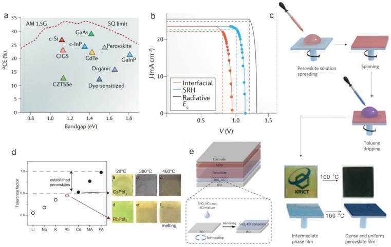
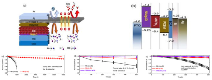
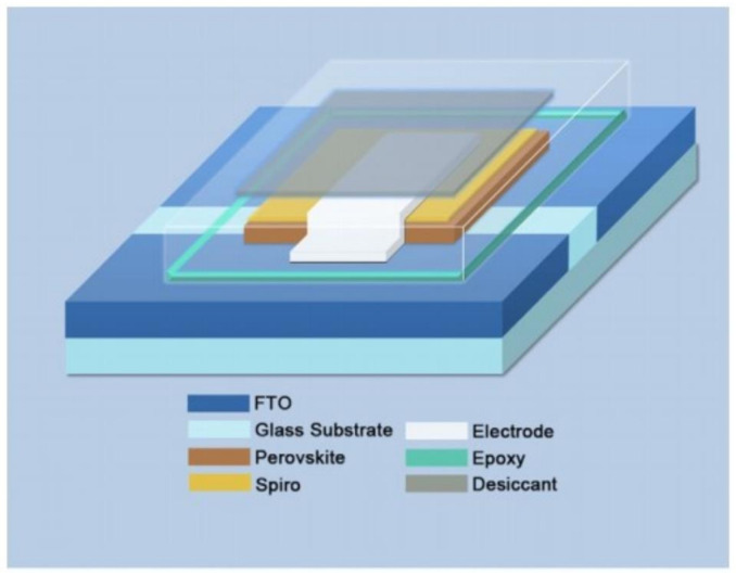
In recent years, perovskite solar cells (PSCs) have experienced rapid development and have presented an excellent commercial prospect as the PSCs are made from raw materials that are readily and cheaply available depending on simple manufacturing techniques. However, the commercial production and utilization of PSCs remain immature, leading to substantial efforts needed to boost the development of scalable fabrication of PSCs, pilot scale tests, and the establishment of industrial production lines. In this way, the PSCs are expected to be successfully popularized from the laboratory to the photovoltaic market. In this review, the history of power conversion efficiency (PCE) for laboratory-scale PSCs is firstly introduced, and then some methods for maintaining high PCE in the upscaling process is displayed. The achievements in the stability and environmental friendliness of PSCs are also summarized because they are also of significance for commercialization. Finally, this review evaluates the commercialization prospects of PSCs from the economic view and provides a short outlook.

Keywords: commercial promotion; fabrication technique; perovskite solar cells (PSCs); power conversion efficiency (PCE).


Conflict of interest statement

The authors declare no conflict of interest.

Figures

Figure 2
Figure 2
(a) PCE limit as a function of the bandgap for single junction solar cells calculated using the Shockley–Queisser (SQ) theory [25]. (not fully updated) (b) J-V curves for PSCs with different carrier recombination mechanisms [24]. (c) Solvent engineering procedure for preparing the uniform and dense perovskite film [26]. (d) Tolerance factor and perovskites at different temperatures with Rb doping [27]. (e) Device structure of planar PSCs and schematic fabrication process of SnO2-KCl composite ETL [31].
Figure 3
Figure 3
(a,b) Illustration of perovskite films deposited by the pressure-assisted processing method and by the spin-coating method [33]. (c) Blade-coating method [36]. (d) Slot-die coating method [36]. (e) Spray-coating method [36]. (f) Inkjet printing method [36]. (g) Screen printing method [36]. (h) Pie chart of the methods in the PSM fabrication (Data sources from Table S1) (not fully updated).
Figure 4
Figure 4
(a) Morphological characterization of perovskite MAPbI3 films without and with 3% Cl incorporation by optical microscopy and scanning electron microscopy [87]. (b) A photographic image of blade-coated perovskite films without and with LP surfactant [37]. (c) The schematic diagram of the static antisolvent process and dynamic antisolvent quenching process [100]. (d,e) Blade-coated perovskite films on indium tin oxide (ITO) coated with Willow Glass with N2 gas to improve film morphology [105].
Figure 5
Figure 5
(a) Interconnection of a perovskite module fabricated by typical scribing processes for thin-film solar modules. [36] (b) In 2018, Deng et al. obtained PSMs with a PCE of 15.3% (aperture area 33 cm2) [37]. (c) In 2019, Qiu et al. obtained PSMs with a PCE of 12.3% (aperture area 22.8 cm2) [117] and (d) in 2020, Ren et al. obtained PSMs with a PCE of 17.88% (aperture area 25.49 cm2) [23].
Figure 6
Figure 6
(a) Stability characteristics of the PSCs with PEDOT:PSS and PEDOT:GO composite films under ambient air conditions [42]; long-term stability result of devices with (b) PEDOT:PSS, a-PEDOT:PSS, ap-PEDOT:PSS [124], and (c) a-GO, GO [124], stored in N2 atmosphere; (d) the scheme of the structure of the device fabricated with rGO-added HTL and the stability test results [133]; the molecular structure of (e) P1 [134], (f) P2 [134]; (g) the stability test of devices with P1 or P2 [134]; (h) the molecular structure of EH44 [135]; (i) the operational stability test of TiO2/FAMACs/Spiro-OMeTAD or EH44/Au devices under ambient conditions [135].
Figure 7
Figure 7
(a) Energy level diagram of PSCs with NiOx and Ag:NiOx HTLs [29]. (b) Stability test of the of PSCs based on NiOx and Ag:NiOx (5 mol %) as a function of storage (N2 box in the dark) time [29], (c) Stability test of PEDOT:PSS-based devices, NiOx-based devices and Ag:NiOx (2 at.%)-based devices [139].
Figure 8
Figure 8
(a) The energy-level diagram of a typical device structure involving CuOx [143]; (b) the stability test of PEDOT:PSS-based and CuOx-based devices, the normalized PCE decay of devices based on various HTLs [143]; (c)The energy-level diagram of a typical device structure involving MnS [144]; (d) under dark conditions [144]; (e) under continuous 1-sun illumination (100 mW cm−2) at room temperature in ambient air; [144] (f) thermal stability of PSCs at a maximum power point under continuous 1-sun illumination at 85 °C in ambient air [144].
Figure 9
Figure 9
(a) Schematic diagram of the interaction between PEG and SnO2 [145], (b) the illustration of the energy band alignment of SnO2, NH4Cl-SnO2, and the perovskite layer [146], (c) the stability test of SnO2-based and NH4Cl-SnO2-based devices [146], (d) the stability test of PCBM-based devices and rGO:PCBM-based devices [147]; the stability test of TiO2-based devices and SnO2/TiO2-based devices (e) under continuous light illumination at room temperature [18], and (f) under continuous UV light illumination inside a dry air box [18].
Figure 10
Figure 10
(a) Light stability of opaque perovskite cells on FTO substrates with different cation compositions upon 12 h under continuous 1-sun illumination [159]. (b) Long-term stabilities of the best perovskite devices stored under ambient air conditions without encapsulation for longer than 1000 h. [160] SEM images of (c) FAMA [160], (d) CsFAMA [160], and (e) KCsFAMA [160] perovskite films. The scale bar is 1 mm.
Figure 11
Figure 11
(a) Long-term stability of perovskite devices with different 2D additives under light illumination without encapsulation [165]. (b) Arrhenius plots (obtained by linear fitting of data points) of the temperature dependence of T/τ, showing an ion migration activation energy (Ea) for pristine films and films with AALs, respectively [166]. (c) Long-term stability of the pristine CsFAMA device and the CsFAMA device with AALs under constant simulated solar illumination (100 mW cm−2) in a N2 atmosphere with a UV filter with a 420-nm cut-off [166].
Figure 12
Figure 12
(a) Schematic diagram of the device structure; the Bi interlayer has a superior shielding capability, prohibiting both inward and outward permeation [179]. (b) Energy level diagram and diagram of the device [179], Stability test of unencapsulated devices (c) stored in the dark in ambient air at RT without humidity control, and J–V curves acquired periodically in ambient air [179]; (d) aged in the dark at 85 °C in a N2 atmosphere, and J–V curves acquired periodically in ambient air [179]; (e) aged under continuous illumination in a N2 atmosphere with electrical biases (0.641–0.885 V) near MPP at a cell temperature of 45 °C. The light intensity for aging was generated by a white light LED array and calibrated to achieve the same JSC from the devices as for 1-sun AM1.5G solar irradiation [179].
Figure 13
Figure 13
(a) Stability test of Au-based devices and self-adhesive microporous carbon (C2)-based devices kept in ambient atmosphere without any encapsulation [184], (b) Long-term aging test under constant illumination and MPP in N2 atmosphere at 20 °C. The inset shows the detailed degradation characteristics of C2-PSCs during the first 10 h [184]; Efficiency stability of the standard and all-carbon electrode-based flexible PSCs as a function of soaking time under different conditions (c) in ambient atmosphere under AM 1.5G illumination in air without a UV filter [180], and (d) in ambient atmosphere with constant heating temperature of 60 °C [180].
Figure 14
Figure 14
The encapsulation strategies of PSCs [189].
Figure 15
Figure 15
The cost proportion of materials used in laboratory small-area PSCs.
Figure 16
Figure 16
Cost of material distribution for Module A (left) and Module B (right). The values of materials cost are assumed by the real amount of material used in both the structure and wholesale price. An 80% material usage ratio was considered [225].
Figure 17
Figure 17
Schematic showing the recycling process for MAPbI3 film deposited by (a) single-step chloride and single-step acetate route and (b) sequential deposition route [228].
Figure 1
Figure 1
PCE development process of PSCs [1,2,3,9,10,11,12,13,14,15].

References

    1. Kojima A., Teshima K., Shirai Y., Miyasaka T. Organometal Halide Perovskites as Visible-light Sensitizers for Photovoltaic Cells. J. Am. Chem. Soc. 2009;131:6050–6051. doi: 10.1021/ja809598r. - DOI - PubMed
    1. Kim H.-S., Lee C.-R., Im J.-H., Lee K.-B., Moehl T., Marchioro A., Moon S.-J., Humphry-Baker R., Yum J.-H., Moser J.E. Lead iodide perovskite sensitized all-solid-state submicron thin film mesoscopic solar cell with efficiency exceeding 9% Sci. Rep. 2012;2:1–7. doi: 10.1038/srep00591. - DOI - PMC - PubMed
    1. Best Research-Cell Efficiencies, NREL. [(accessed on 31 July 2021)]; Available online: https://www.nrel.gov/pv/assets/pdfs/best-research-cell-efficiencies-rev2....
    1. Hao F., Stoumpos C.C., Cao D.H., Chang R.P.H., Kanatzidis M.G. Lead-free solid-state organic–inorganic halide perovskite solar cells. Nat. Photonics. 2014;8:489–494. doi: 10.1038/nphoton.2014.82. - DOI
    1. Pellet N., Gao P., Gregori G., Yang T.Y., Nazeeruddin M.K., Maier J., Gratzel M. Mixed-organic-cation perovskite photovoltaics for enhanced solar-light harvesting. Angew. Chem. Int. Ed. 2014;53:3151–3157. doi: 10.1002/anie.201309361. - DOI - PubMed

LinkOut - more resources