

Friction Stir Welding/Processing of Mg-Based Alloys: A Critical Review on Advancements and Challenges
- PMID: 34772249
- PMCID: PMC8588004
- DOI: 10.3390/ma14216726
Friction Stir Welding/Processing of Mg-Based Alloys: A Critical Review on Advancements and Challenges
Abstract
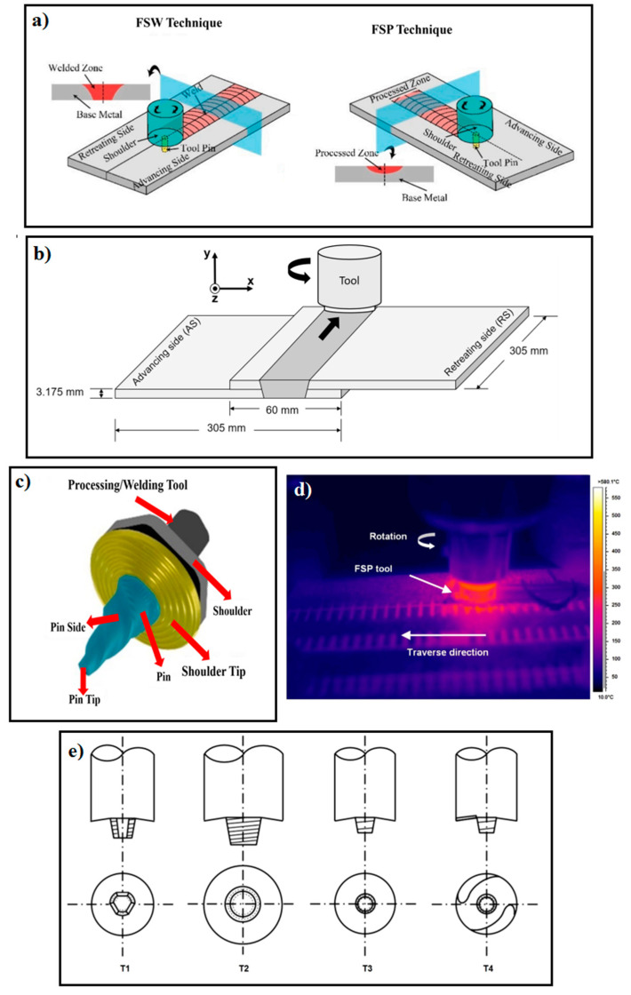
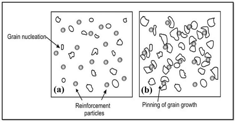
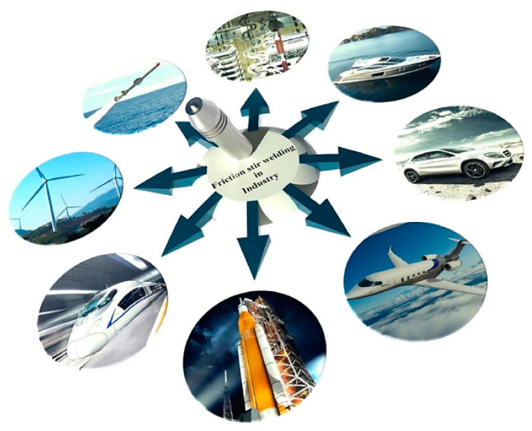
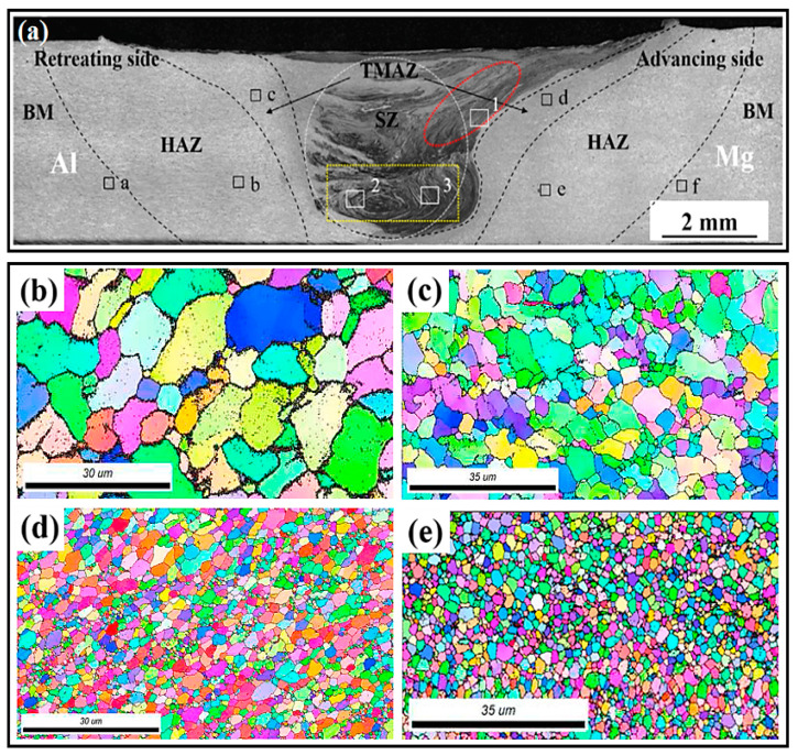
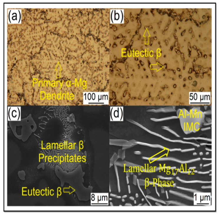
Friction stir welding (FSW) and friction stir processing (FSP) are two of the most widely used solid-state welding techniques for magnesium (Mg) and magnesium alloys. Mg-based alloys are widely used in the railway, aerospace, nuclear, and marine industries, among others. Their primary advantage is their high strength-to-weight ratio and usefulness as a structural material. Due to their properties, it is difficult to weld using traditional gas- or electric-based processes; however, FSW and FSP work very well for Mg and its alloys. Recently, extensive studies have been carried out on FSW and FSP of Mg-based alloys. This paper reviews the context of future areas and existing constraints for FSW/FSP. In addition, in this review article, in connection with the FSW and FSP of Mg alloys, research advancement; the influencing parameters and their influence on weld characteristics; applications; and evolution related to the microstructure, substructure, texture and phase formations as well as mechanical properties were considered. The mechanisms underlying the joining and grain refinement during FSW/FSP of Mg alloys-based alloys are discussed. Moreover, this review paper can provide valuable and vital information regarding the FSW and FSP of these alloys for different sectors of relevant industries.
Keywords: friction stir processing; friction stir welding; magnesium-based alloys; mechanical properties; microstructure; severe plastic deformation; texture.
Conflict of interest statement
The authors declare that they have no competing/financial conflicts of interest in this paper.
Figures
Similar articles
-
A Review on Friction Stir Welding of Copper: Tool Geometry, Process Parameters, and Joint Properties.Materials (Basel). 2024 Nov 3;17(21):5374. doi: 10.3390/ma17215374. Materials (Basel). 2024. PMID: 39517648 Free PMC article. Review.
-
Friction Stir Processing Influence on Microstructure, Mechanical, and Corrosion Behavior of Steels: A Review.Materials (Basel). 2021 Sep 2;14(17):5023. doi: 10.3390/ma14175023. Materials (Basel). 2021. PMID: 34501111 Free PMC article. Review.
-
Friction Stir Welding of Aluminum in the Aerospace Industry: The Current Progress and State-of-the-Art Review.Materials (Basel). 2023 Apr 8;16(8):2971. doi: 10.3390/ma16082971. Materials (Basel). 2023. PMID: 37109809 Free PMC article. Review.
-
Friction Stir Welding of Thick Plates of 4Y3Gd Mg Alloy: An Investigation of Microstructure and Mechanical Properties.Materials (Basel). 2021 Nov 16;14(22):6924. doi: 10.3390/ma14226924. Materials (Basel). 2021. PMID: 34832331 Free PMC article.
-
Investigation of Mechanical and Microstructural Properties of Welded Specimens of AA6061-T6 Alloy with Friction Stir Welding and Parallel-Friction Stir Welding Methods.Materials (Basel). 2021 Oct 12;14(20):6003. doi: 10.3390/ma14206003. Materials (Basel). 2021. PMID: 34683594 Free PMC article.
Cited by
-
Improving the Mechanical Properties of Mg-5Al-2Ca-1Mn-0.5Zn Alloy through Rotary Swaging.Materials (Basel). 2023 Jun 20;16(12):4489. doi: 10.3390/ma16124489. Materials (Basel). 2023. PMID: 37374672 Free PMC article.
-
AZ91 Magnesium Alloy CMT Cladding Layer Processed Using Friction Stir Processing: Effect of Traverse Speed on Microstructure and Mechanical Properties.Materials (Basel). 2024 May 15;17(10):2348. doi: 10.3390/ma17102348. Materials (Basel). 2024. PMID: 38793428 Free PMC article.
-
The Effect of Holding Time on Dissimilar Transient Liquid-Phase-Bonded Properties of Super-Ferritic Stainless Steel 446 to Martensitic Stainless Steel 410 Using a Nickel-Based Interlayer.Micromachines (Basel). 2022 Oct 22;13(11):1801. doi: 10.3390/mi13111801. Micromachines (Basel). 2022. PMID: 36363822 Free PMC article.
-
Corrosion Behavior of CMT Cladding Layer of AZ91 Magnesium Alloy Subjected to Friction Stir Processing.Materials (Basel). 2024 Jun 12;17(12):2875. doi: 10.3390/ma17122875. Materials (Basel). 2024. PMID: 38930245 Free PMC article.
-
Numerical Simulation and Experimental Study on the TIG (A-TIG) Welding of Dissimilar Magnesium Alloys.Materials (Basel). 2022 Jul 15;15(14):4922. doi: 10.3390/ma15144922. Materials (Basel). 2022. PMID: 35888389 Free PMC article.
References
-
- Gotawala N., Kumar A., Mishra S., Shrivastava A. Microstructure and texture evolution of complete Mg-3Al-0.2Ce alloy blanks upon multi-pass friction stir processing with spiral strategy. Mater. Today Commun. 2021;26:101850. doi: 10.1016/j.mtcomm.2020.101850. - DOI
-
- Singh K., Singh G., Singh H. Review on friction stir welding of magnesium alloys. J. Magnes. Alloys. 2018;6:399–416. doi: 10.1016/j.jma.2018.06.001. - DOI
-
- Liu F., Ji Y., Sun Z., Liu J., Bai Y., Shen Z. Enhancing corrosion resistance and mechanical properties of AZ31 magnesium alloy by friction stir processing with the same speed ratio. J. Alloys Compd. 2020;829:154452. doi: 10.1016/j.jallcom.2020.154452. - DOI
-
- Liu Q., Chen G., Zeng S., Zhang S., Long F., Shi Q. The corrosion behavior of Mg-9Al-xRE magnesium alloys modified by friction stir processing. J. Alloys Compd. 2021;851:156835. doi: 10.1016/j.jallcom.2020.156835. - DOI
-
- Chen T., Chen Z., Shao J., Wang R., Mao L., Liu C. The role of long-period stacking ordered phases in the deformation behavior of a strong textured Mg-Zn-Gd-Y-Zr alloy sheet processed by hot extrusion. Mater. Sci. Eng. A. 2019;750:31–39. doi: 10.1016/j.msea.2019.02.040. - DOI
Publication types
LinkOut - more resources
Full Text Sources
