

Electrode montage-dependent intracranial variability in electric fields induced by cerebellar transcranial direct current stimulation
- PMID: 34773062
- PMCID: PMC8589967
- DOI: 10.1038/s41598-021-01755-9
Electrode montage-dependent intracranial variability in electric fields induced by cerebellar transcranial direct current stimulation
Abstract
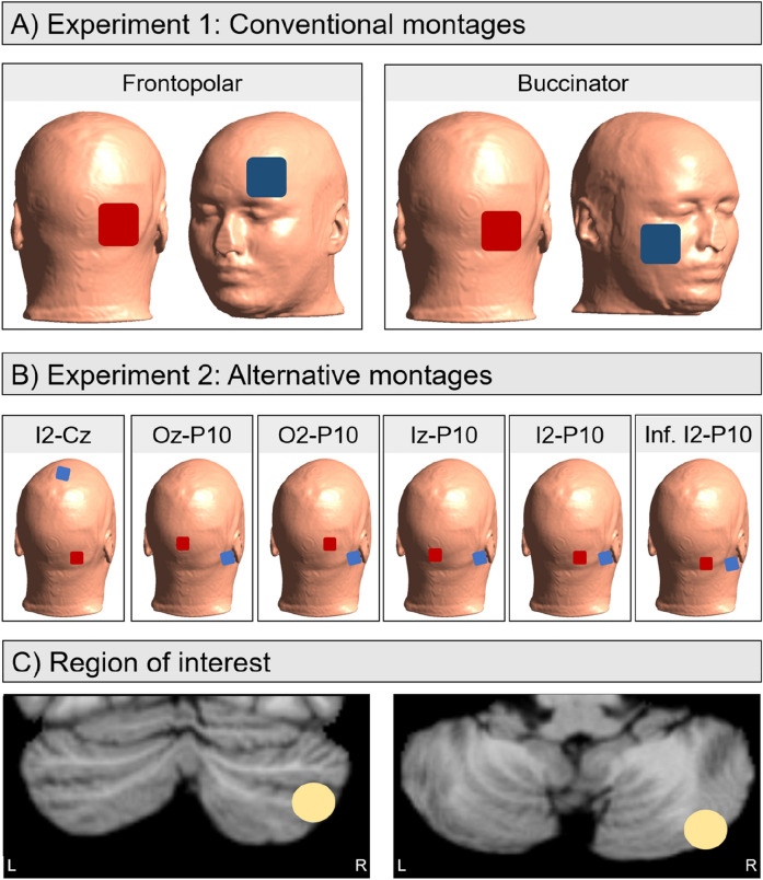
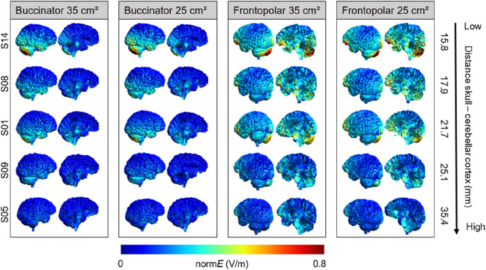
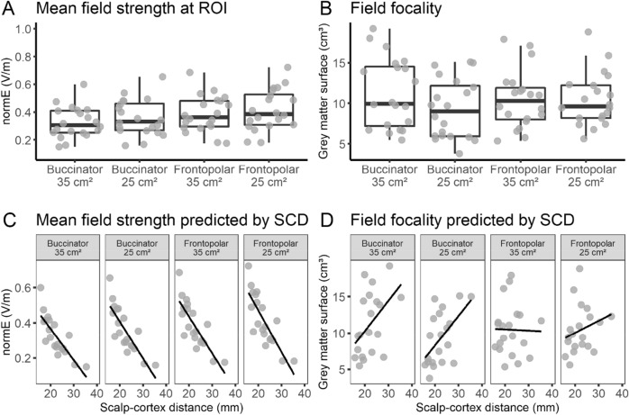
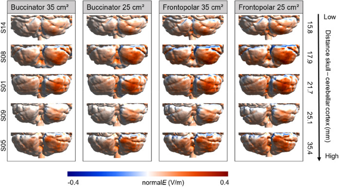
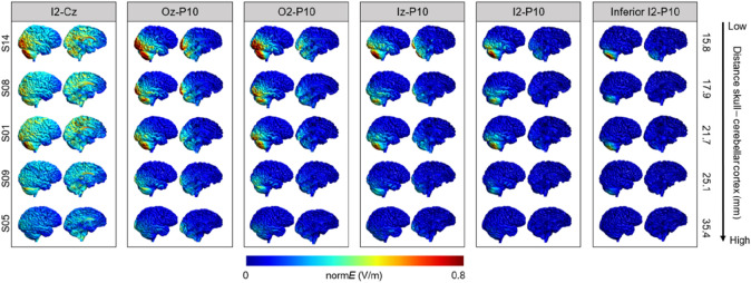
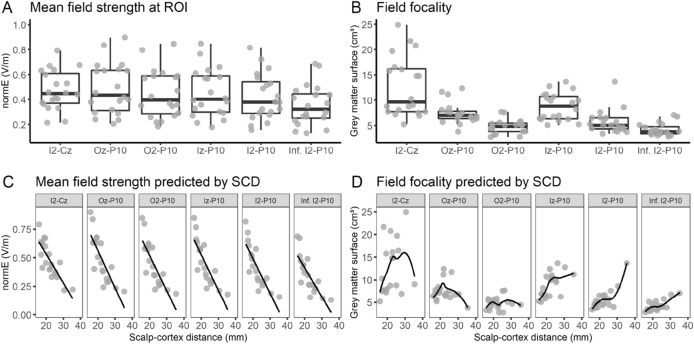
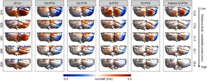
Transcranial direct current stimulation (tDCS) is an increasingly popular tool to investigate the involvement of the cerebellum in a variety of brain functions and pathologies. However, heterogeneity and small effect sizes remain a common issue. One potential cause may be interindividual variability of the electric fields induced by tDCS. Here, we compared electric field distributions and directions between two conventionally used electrode montages (i.e., one placing the return electrode over the ipsilateral buccinator muscle and one placing the return electrode [25 and 35 cm2 surface area, respectively] over the contralateral supraorbital area; Experiment 1) and six alternative montages (electrode size: 9 cm2; Experiment 2) targeting the right posterior cerebellar hemisphere at 2 mA. Interindividual and montage differences in the achieved maximum field strength, focality, and direction of current flow were evaluated in 20 head models and the effects of individual differences in scalp-cortex distance were examined. Results showed that while maximum field strength was comparable for all montages, focality was substantially improved for the alternative montages over inferior occipital positions. Our findings suggest that compared to several conventional montages extracerebellar electric fields are significantly reduced by placing smaller electrodes in closer vicinity of the targeted area.
© 2021. The Author(s).
Conflict of interest statement
The authors declare no competing interests.
Figures
Similar articles
-
Interindividual differences in posterior fossa morphometry affect cerebellar tDCS-induced electric field strength.Clin Neurophysiol. 2023 Sep;153:152-165. doi: 10.1016/j.clinph.2023.06.019. Epub 2023 Jul 14. Clin Neurophysiol. 2023. PMID: 37499446
-
Cost of focality in TDCS: Interindividual variability in electric fields.Brain Stimul. 2020 Jan-Feb;13(1):117-124. doi: 10.1016/j.brs.2019.09.017. Epub 2019 Oct 2. Brain Stimul. 2020. PMID: 31606449
-
Putting focus on transcranial direct current stimulation in language production studies.PLoS One. 2018 Aug 23;13(8):e0202730. doi: 10.1371/journal.pone.0202730. eCollection 2018. PLoS One. 2018. PMID: 30138361 Free PMC article.
-
Transcranial direct current stimulation in obsessive-compulsive disorder: an update in electric field modeling and investigations for optimal electrode montage.Expert Rev Neurother. 2019 Oct;19(10):1025-1035. doi: 10.1080/14737175.2019.1637257. Epub 2019 Jul 8. Expert Rev Neurother. 2019. PMID: 31244347 Review.
-
Cerebellar tDCS: how to do it.Cerebellum. 2015 Feb;14(1):27-30. doi: 10.1007/s12311-014-0599-7. Cerebellum. 2015. PMID: 25231432 Free PMC article. Review.
Cited by
-
Non-invasive Brain Stimulation of the Cerebellum in Emotion.Adv Exp Med Biol. 2022;1378:109-121. doi: 10.1007/978-3-030-99550-8_8. Adv Exp Med Biol. 2022. PMID: 35902468
-
Consensus Paper: Cerebellum and Ageing.Cerebellum. 2024 Apr;23(2):802-832. doi: 10.1007/s12311-023-01577-7. Epub 2023 Jul 10. Cerebellum. 2024. PMID: 37428408 Free PMC article. Review.
-
Transcranial Direct Current Stimulation for Chronic Stroke: Is Neuroimaging the Answer to the Next Leap Forward?J Clin Med. 2023 Mar 30;12(7):2601. doi: 10.3390/jcm12072601. J Clin Med. 2023. PMID: 37048684 Free PMC article. Review.
-
Exciting the social butterfly: Anodal cerebellar transcranial direct current stimulation modulates neural activation during predictive social mentalizing.Int J Clin Health Psychol. 2024 Jul-Sep;24(3):100480. doi: 10.1016/j.ijchp.2024.100480. Epub 2024 Jul 4. Int J Clin Health Psychol. 2024. PMID: 39055855 Free PMC article.
-
Optimising Electrode Montages in Conventional Transcranial Direct Current Stimulation and High-Definition Transcranial Direct Current Stimulation of the Cerebellum for Pain Modulation.Brain Sci. 2025 Mar 27;15(4):344. doi: 10.3390/brainsci15040344. Brain Sci. 2025. PMID: 40309808 Free PMC article.
References
-
- Nitsche MA, Paulus W. Transcranial direct current stimulation—Update 2011. Restor. Neurol. Neurosci. 2011;29:463–492. - PubMed
Publication types
MeSH terms
Grants and funding
LinkOut - more resources
Full Text Sources
