Review
. 2021 Oct 21:23:101649.
doi: 10.1016/j.jcot.2021.101649. eCollection 2021 Dec.

Imaging update in arthroplasty

Affiliations
Review

Imaging update in arthroplasty

Nicholas Ong et al. J Clin Orthop Trauma. .

Abstract

Imaging of metal implants has historically been difficult, regardless of the applied modality. The number of primary arthroplasties is increasing over the years. With it, we expect the number of symptomatic complications to increase as well. Acquiring accurate imaging for diagnosis and treatment planning for these cases is of paramount importance. Significant advancements have been made to reduce artifacts, leading to better imaging representation of arthroplasty. This review article would give a background on the current ways of imaging arthroplasty and metal implants, covering recent advances in imaging techniques.

Keywords: Arthroplasty; CT scan; MRI; Metal artifact reduction techniques; Orthopedic implants; Radiographs.


Figures

Fig. 1a
Fig. 1a
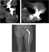
Iterative metal artifact reduction (iMAR) sequence of a proximal femoral nail antirotation implant using proprietary Siemens algorithm. Note the reduction in beam hardening artifacts.
Fig. 1b
Fig. 1b
iMAR image of a left total hip arthroplasty performed using the same Siemens algorithm in Fig 1a. Note the increased residual beam hardening artifacts due to the difference in implant type.
Fig. 2a
Fig. 2a
Computed tomography of posterior spinal instrumenta'on from fusion of L2 to S1 without dual energy sequences.
Fig. 2b
Fig. 2b
Dual energy computed tomography of the same patient. Note the reduction in beam hardening artifact and better visualization of the interface between implant screws and adjacent bone in comparison to Fig 2a.
Fig. 3
Fig. 3
MRI of the left ankle with screw fixation of a talus fracture. O-MAR sequencing using a 1.5T Philips scanner reduces the metallic susceptibility artifact of the talar screws and shows the interface between the implant and surrounding bone.
Fig. 4
Fig. 4
(A) radiograph of the right wrist with periprosthetic lucencies (B) corresponding ultrasound of the same patient demonstrating an irregular thick walled collection with echogenic contentsin the vicinity of the metallic prosthesis likely representing a pseudotumor related to metallosis.
Fig. 5
Fig. 5
Radiograph of the left elbow post internal fixation of a radial fracture with corresponding dual energy computed tomography images illustrating the areas of marrow oedema (depicting osteomyelitis) represented by green colour coding around the implant site at the proximal radius and ulna.
Fig. 6
Fig. 6
(A) Initial post-operative radiograph of the left knee following total knee replacement surgery. (B) Radiograph of the same patient 9 years post implantation showing significant implant subsidence (C) Corresponding computed tomography of the lower extremity also demonstrates gas within the cement adjacent to the tibial implant indicative of infective changes with chronic changes of osteomyelitis also shown.
Fig. 7
Fig. 7
Coronal magnetic resonance imaging of the pelvis with MARS sequencing in a patient post uncemented bilateral hip arthroplasty with suspicion of joint infection due to complaints of hip pain a year post implantation. Oedema is present in the right hip joint and adjoining soft tissue supporting this diagnosis.
Fig. 8
Fig. 8
(A) Initial radiograph following total ankle replacement (B and C) Subsequent radiograph and computed tomography images demonstrating talar plate subsidence with medial migration resulting in incongruency with the tibial plate.
Fig. 9
Fig. 9
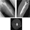
Computed tomography and corresponding plain radiograph of a left total hip replacement implant demonstrating implant subsidence. Depression of the medial tip of the prosthetic shoulder in relation to the lesser trochanter.
Fig. 10a
Fig. 10a
(A) CT derived surgical transepicondylar axis (CTsTEA); the line drawn from the most prominent part of the lateral epicondyle to the sulcus in the medial epicondyle (B) Femoral component rotational axis (FCRA) is the common tangent of the two pegs on the inside of the femoral component. Superimposing the CTsTEA on the same axial image we get the femoral component rotational angle (FCR angle) of zero degrees in this case.
Fig. 10b
Fig. 10b
Berger method for tibial component rotation measurement. (A) 2D axial CT at the level of the tibial plateau identifying the geometric centre [GC] (B) a line is then drawn from the GC to the tibial tuberosity [TT] (C) the line from the GC to TT is transposed to an axial image at the tibial tray. The angle between this line and the tibial component axis illustrates the extent of external rotation rela've to the tip of the tibial tubercle. Eighteen degrees in this case.
Fig. 11
Fig. 11
Computed tomography of the left hip following a hemiarthroplasty. Bony fragmentation noted at the anterior acetabular column in keeping with a periprosthetc fracture.
Fig. 12
Fig. 12
(A) plain radiograph of left femur following bipolar hemiarthroplasty (B and C) corresponding computed tomography images. Heterotopic ossification of the adjacent soft tissue lateral to the mid shaft of the femur along the distal femoral implant site.
Fig. 13
Fig. 13
Pseudotumor in the right hip. (A) right hip radiograph post total hip arthroplasty (B) corresponding CT scan of the same patient showing osteolysis in the acetabulum, iliac bone and ischium around the prosthesis along with a well circumscribed homogenous mass lesion in keeping with a pseudotumor.
Fig. 14
Fig. 14
Pseudotumor in the left hip following total hip replacement surgery. (A, C) Axial T1 weighted (C) post contrast and (B, D) STIR (B) with SEMAC (metal reduction sequence) showing a lobulated collection with high signal intensity fluid and intermediate to low signal intensity debris along with osteolysis. This is seen to be in communication with the arthroplasty hardware.
Fig. 15
Fig. 15
(A) Initial post-operative plain radiograph of a left hip proximal femoral nail antirotation implant. (B) Subsequent hip radiograph and corresponding computed tomography images of the same patient two years after implantation. Note the implant loosening with increased lucent margin around the lag screw at the femoral head component and increased varus tilt of the intramedullary nail.

References

    1. Kurtz S., Ong K., Lau E., Mowat F., Halpern M. Projections of primary and revision hip and knee arthroplasty in the United States from 2005 to 2030. J Bone Jt Surg - Ser A. 2007;89(4):780–785. doi: 10.2106/JBJS.F.00222. - DOI - PubMed
    1. Mulhall K.J., Masterson E., Burke T.E. Routine recovery room radiographs after total hip arthroplasty: ineffective for screening and unsuitable as baseline for longitudinal follow-up evaluation. J Arthroplasty. 2004;19(3):313–317. doi: 10.1016/j.arth.2003.08.021. - DOI - PubMed
    1. Vanrusselt J., Vansevenant M., Vanderschueren G., Vanhoenacker F. Postoperative radiograph of the hip arthroplasty: what the radiologist should know. Insights Imaging. 2015;6(6):591–600. doi: 10.1007/s13244-015-0438-5. - DOI - PMC - PubMed
    1. Robertson D.D., Weiss P.J., Fishman E.K., Magid D., Walker P.S. Evaluation of CT techniques for reducing artifacts in the presence of metallic orthopedic implants. J Comput Assist Tomogr. 1988;12(2):236–241. doi: 10.1097/00004728-198803000-00012. - DOI - PubMed
    1. Katsura M., Sato J., Akahane M., Kunimatsu A., Abe O. Current and novel techniques for metal artifact reduction at CT: practical guide for radiologists. Radiographics. 2018;38(2):450–461. doi: 10.1148/rg.2018170102. - DOI - PubMed

LinkOut - more resources