. 2021 Nov 17;11(1):22435.
doi: 10.1038/s41598-021-01184-8.

Offset of openings in optic nerve head canal at level of Bruch's membrane, anterior sclera, and lamina cribrosa

Affiliations

Offset of openings in optic nerve head canal at level of Bruch's membrane, anterior sclera, and lamina cribrosa

Kyoung Min Lee et al. Sci Rep. .

Abstract

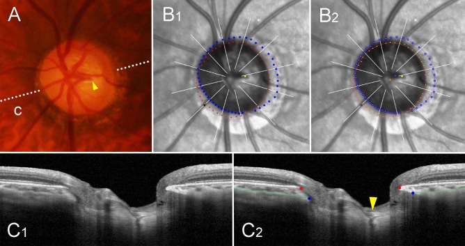
We compared the central retinal vascular trunk (CRVT) position, as a surrogate of lamina cribrosa (LC) offset, with the anterior scleral opening (ASCO) offset from the Bruch's membrane opening (BMO). Based on the BMO-centered radial scans, the BMO and ASCO margins were demarcated, and each center was determined as the center of the best-fitted ellipse for each margin. The ASCO/BMO offset was defined as the offset between each center. Angular deviations and the extent of ASCO and CRVT offsets from the BMO center were compared directly. Incomplete demarcation of ASCO was found in 20%, which was associated with a larger BMO area and a larger ASCO offset from the BMO. The angular deviation of ASCO offset was associated with that of CRVT offset and that of the longest externally oblique border. The ASCO offset was smaller than the CRVT offset, and, unlike the CRVT offset, it was rarely deviated to the inferior side. The complete ASCO margin might not be demarcatable when determined on BMO-centered radial scans in the presence of an offset. Also, the ASCO, which reflects only the superficial scleral layer, might not reflect the LC position, because the LC might be shifted further from the ASCO.


Conflict of interest statement

The authors declare no competing interests.

Figures

Figure 1
Figure 1
Schematic drawing of three openings in optic nerve head (ONH) canal. The black lines indicate the Bruch’s membrane (BM) with central opening (BMO). The blue lines indicate the sclera and its anterior opening, defined as the anterior scleral opening (ASCO; blue circle). The lamina cribrosa (LC; purple cylinder) is located at a lower level than the ASCO is. The axons passing through the ONH canal are drawn as yellow fibers. The central retinal vascular trunk (CRVT; red line) also passes through the ONH canal. The optic nerve sheath (gray line) is anchored to the posterior sclera near the ONH canal. The alignments among the BMO, ASCO, and LC are known to change during eyeball expansion. This study was designed to compare the ASCO and CRVT (a surrogate of LC position) offsets from the BMO.
Figure 2
Figure 2
Offsets of anterior scleral opening (ASCO), central retinal vascular trunk (CRVT), and longest externally oblique border (EOB). (A, B) Vector fields comparing the CRVT (orange arrows) and the ASCO offsets (blue arrows) in eyes with complete ASCO demarcation (A) and in eyes with incomplete ASCO demarcation (B). Both offsets share directionalities, while extent is larger for CRVT offset than for ASCO offset. Please note that the eyes with the largest CRVT offset (shift index = 1.0) are not even drawn in the vector fields because we could not define the directionality for the CRVT offset in those cases. (C) Scatter plot comparing extent of CRVT and ASCO offsets within individuals by pixels. Regardless of complete or incomplete ASCO demarcation, CRVT offset tends to be larger than ASCO offset. The eyes with the largest CRVT offset (shift index = 1.0) were excluded from the analysis because we could not measure the exact pixel values of CRVT offset in those cases. (D) Scatter plot comparing angular deviations of CRVT offset, ASCO offset, and longest EOB. Please note that ASCO offset is barely deviated inferiorly. S = superior; T = temporal; I = inferior; N = nasal.
Figure 3
Figure 3
Sample case of outer-wall shift to nasal side (left eye of 47-year-old man with glaucoma, axial length of 26.68 mm). (A) Disc photograph. The arrowhead indicates the location of the central retinal vascular trunk (CRVT). The dotted lines indicate the location of the OCT scan. (B) Infrared images. (B1) Bruch’s membrane opening (BMO, red dots), anterior scleral opening (ASCO, blue dots), CRVT position (yellow dot), and meridian of longest externally oblique border (EOB, black dot) are marked. (B2) Best-fitted ellipses for BMO (orange ellipse) and ASCO (purple ellipse) are drawn with their centers (orange dot for BMO center, purple dot for ASCO center). (C) B-scan OCT images (top row: original images, bottom row: images with labels). The red dots indicate the BMO margin; the blue dots indicate the ASCO margin; the green lines indicate the anterior scleral surface; the arrowhead indicates the CRVT. On the nasal side, the ASCO margin cannot be drawn (C1, C2, question mark). The ASCO margin can be drawn on the adjacent scan (C3). Since the indiscernible angle is larger than 30° on the nasal side, this eye is classified as incomplete demarcation for ASCO and grouped accordingly. Despite the incomplete ASCO demarcation, the best-fitted ellipse could be fitted, and the boundary according to the fitting is marked by the purple dotted lines (C1, C2). Please note that both the CRVT and ASCO offsets are headed nasally, while the extent is larger for the CRVT offset than for the ASCO offset.
Figure 4
Figure 4
Sample case of outer-wall shift to superior side (left eye of 44-year-old man with glaucoma, axial length of 25.36 mm). (A) Disc photograph. The arrowhead indicates the location of the central retinal vascular trunk (CRVT). The dotted lines indicate the location of the OCT scan. (B) Infrared images. (B1) Bruch’s membrane opening (BMO, red dots), anterior scleral opening (ASCO, blue dots), CRVT position (yellow dot), and meridian of longest externally oblique border (EOB, black dot) are marked. (B2) Best-fitted ellipses for BMO (orange ellipse) and ASCO (purple ellipse) are drawn with their centers (orange dot for BMO center, purple dot for ASCO center). (C) B-scan OCT images (top row: original images, bottom row: images with labels). The red dots indicate the BMO margin; the blue dots indicate ASCO margin; the green lines indicate the anterior scleral surface; the arrowhead indicates the CRVT. The ASCO margin is completely demarcatable, and thus, this eye is classified into the complete demarcation group for ASCO. Please note that both the CRVT and ASCO offsets are headed superiorly, while the extent is larger for the CRVT offset than for the ASCO offset.
Figure 5
Figure 5
Sample case of outer-wall shift to temporal side (left eye of 59-year-old woman with glaucoma, axial length of 26.35 mm). (A) Disc photograph. The arrowhead indicates the location of the central retinal vascular trunk (CRVT). The dotted lines indicate the location of the OCT scan. (B) Infrared images. (B1) Bruch’s membrane opening (BMO, red dots), anterior scleral opening (ASCO, blue dots), CRVT position (yellow dot), and meridian of longest externally oblique border (EOB, black dot) are marked. (B2) Best-fitted ellipses for BMO (orange ellipse) and ASCO (purple ellipse) are drawn with their centers (orange dot for BMO center, purple dot for ASCO center). (C) B-scan OCT images. (C1) original image. (C2) image with labels, which clearly shows emergence of CRVT (arrowhead). The green lines indicate the anterior scleral surface. Please note that both the CRVT and ASCO offsets are headed temporally, while the extent is larger for the CRVT offset than for the ASCO offset.
Figure 6
Figure 6
Sample case of outer-wall shift to inferonasal side (left eye of 58-year-old woman with glaucoma, axial length of 23.94 mm). (A) Disc photograph. The arrowhead indicates the location of the central retinal vascular trunk (CRVT). The dotted lines indicate the location of the OCT scan. (B) Infrared images. (B1) Bruch’s membrane opening (BMO, red dots), anterior scleral opening (ASCO, blue dots), and CRVT position (yellow dot) are marked. (B2) Best-fitted ellipses for BMO (orange ellipse) and ASCO (purple ellipse) are drawn with their centers (orange dot for BMO center, purple dot for ASCO center). (C) B-scan OCT images. The left column shows OCT images with demarcation of the BMO margin (red dots) and ASCO margin (blue dots). The green lines indicate the anterior scleral surface. The arrowhead indicates the CRVT. The middle column shows unlabeled OCT images. The right column shows OCT images with demarcation of the peripapillary border tissue of the choroid (PBT-C, upper part of yellow dotted lines) and that of the scleral flange (PBT-S, lower part of yellow dotted lines). The green arrows indicate the ASCO margin, which connects the PBT-C and PBT-S. Please note that the outer-wall shift to the nasal (C1) and inferior (C2) sides is more severe in the more-outer layer (the lamina cribrosa [LC] with CRVT) than in the superficial layer (ASCO), and is presented as an abrupt change between the PBT-C and the PBT-S. This could explain why the CRVT alone is deviated while the ASCO is immediately next to the BMO in this case.
Figure 7
Figure 7
Schematic illustration of optic nerve head (ONH) canal in absence (A) and presence (B) of outer-wall shift. The intervening choroid is omitted for clarity. (Top) Three-dimensional view. A black overlying plane indicates the Bruch’s membrane opening (BMO), and the underneath cuboid with central hole indicates the scleral part of the ONH canal with the anterior scleral opening (ASCO) on the surface. (Bottom) Cross-sectional view. The red dots indicate the BMO margin, the blue dots the ASCO margin, the green dots the anterior lamina cribrosa (LC) insertion site, and the red lines the central retinal vascular trunk (CRVT). The peripapillary border tissue of the choroid (PBT-C) is the black line between the red and blue dots, and the peripapillary border tissue of the scleral flange (PBT-S) is the black line between the blue and green dots. The ASCO/BMO offset is the misalignment between the red and blue dots, and the LC/BMO offset, between the red and green dots. As the LC is located in a lower part of the ONH canal than the ASCO is, the LC/BMO offset is generally larger than the ASCO/BMO offset if the PBT-C and the PBT-S share a common directionality (B, Middle). If the PBT-S rotates further than the PBT-C, however, the LC/BMO offset can increase independently of the ASCO/BMO offset (B, Bottom; green arrow). We speculated that this could happen, due to the fact that the upper layer (the posterior polar retinal structure) is selectively affected by the restriction against expansion, whereas the lower layer (sclera and LC) is not.
Figure 8
Figure 8
Critical disadvantage of determining anterior scleral opening (ASCO) based on radial scans centered on Bruch’s membrane opening (BMO) (right eye of 55 year-old-man without glaucoma, axial length of 25.50 mm). (A) Disc photograph. The dotted lines indicate the location of the OCT scan. (B) Infrared images. (B1) Bruch’s membrane opening (BMO, red dots), anterior scleral opening (ASCO, blue dots), and meridian of longest externally oblique border (EOB, black dot) are marked. (B2) Best-fitted ellipses for BMO (orange ellipse) and ASCO (purple ellipse) are drawn with their centers (orange dot for BMO center, purple dot for ASCO center). (C) B-scan OCT images. (top row: original images, bottom row: images with labels). The red dots indicate the BMO margin; the blue dots indicate the ASCO margin; the green lines indicate the anterior scleral surface. Please note that the B-scans between the red-dotted lines (B2) cannot yield any information about the ASCO, because they simply cannot capture the optic nerve canal at all (C2). Also, the B-scans between the blue-dotted lines (B2) produce uneven sampling for the ASCO: the ASCO margin closer to the BMO center (orange dot) is clustered within a very limited range (B2). Therefore, the ASCO itself is largely influenced by the ASCO/BMO offset, because no radial scans can focus on two different centers simultaneously. In this context, the ASCO/BMO offset as defined by BMO-oriented radial scans has irreparable disadvantage.
Figure 9
Figure 9
Tethering effect by optic nerve sheath during adduction, abduction, supraduction, and infraduction of right eye. During adduction, the anterior part of the eyeball is rotated nasally, which results in the rotation of the posterior pole (the dashed red cross) temporally (the red curved arrow) and subsequent traction to the scleral part of the ONH nasally (the blue arrow). Since the optic nerve sheath is attached to the posterior sclera, this effect will be larger in the deeper scleral part (the LC) than in the superficial part (the ASCO) of the ONH canal. Distally, the optic nerve sheath is anchored to the optic canal, which is located in the nasal and superior sides from the eyeball. Therefore, this tethering effect will be greater during adduction (nasal traction) and supraduction (superior traction) with a straightened path.
Figure 10
Figure 10
Determination of Bruch’s membrane opening (BMO), anterior scleral opening (ASCO), and central retinal vascular trunk (CRVT) (left eye of 65-year-old man without glaucoma, axial length of 23.72 mm). (A) Disc photograph and OCT image. The white dotted line indicates the location of the OCT scan, as targeted to the CRVT (arrowheads). The B-scan OCT image clearly shows the emergence of the CRVT. The red dots indicate the BMO margin. The ASCO margin (blue dots) was determined as the termination of the anterior scleral surface (green lines) at the optic nerve head canal. (B) Infrared image obtained by OCT. The margins of the BMO (red dots) and ASCO (blue dots) are demarcated. The CRVT position (yellow dot) and the meridian of the longest externally oblique border (EOB, black dot) are marked on the same infrared image. (C) Optimal ellipse fitting to obtain BMO and ASCO centers. Recognition of every point by our software is expressed by an inner white dot. The best-fitted ellipse for the BMO (orange ellipse) and the ASCO (purple ellipse) are drawn in reference to their centers (orange dot for BMO center, purple dot for ASCO center). (D) Calculation of offsets from given set of dots. From the BMO center (orange dot), the angular deviation of CRVT (yellow arrow), and ASCO center (purple arrow) are measured clockwise, with the nasal horizontal midline as 0°. A positive value indicates the superior location and a negative value indicates the inferior location. Likewise, the meridian of the longest EOB (black arrow) is measured clockwise, with the temporal horizontal midline as 0°. A positive value indicates the superior location and a negative value indicates the inferior location. From the BMO center, the distances are measured to the CRVT (a) and to the BMO margin in the same direction (b). The ratio of these distances is defined as the “shift index” (a/b), which is used to measure the extent of shift. The extent of CRVT offset (yellow arrow) divided by that of ASCO offset (purple arrow) is defined as the “offset ratio”.

Similar articles

Cited by

References

    1. Strouthidis NG, et al. Comparison of clinical and spectral domain optical coherence tomography optic disc margin anatomy. Invest. Ophthalmol. Vis. Sci. 2009;50:4709–4718. doi: 10.1167/iovs.09-3586. - DOI - PMC - PubMed
    1. Reis AS, et al. Optic disc margin anatomy in patients with glaucoma and normal controls with spectral domain optical coherence tomography. Ophthalmology. 2012;119:738–747. doi: 10.1016/j.ophtha.2011.09.054. - DOI - PMC - PubMed
    1. Sawada Y, et al. Optic disc margin anatomic features in myopic eyes with glaucoma with spectral-domain OCT. Ophthalmology. 2018;125:1886–1897. doi: 10.1016/j.ophtha.2018.07.004. - DOI - PubMed
    1. Chui TY, Zhong Z, Burns SA. The relationship between peripapillary crescent and axial length: Implications for differential eye growth. Vis. Res. 2011;51:2132–2138. doi: 10.1016/j.visres.2011.08.008. - DOI - PMC - PubMed
    1. Dai Y, Jonas JB, Huang H, Wang M, Sun X. Microstructure of parapapillary atrophy: Beta zone and gamma zone. Invest. Ophthalmol. Vis. Sci. 2013;54:2013–2018. doi: 10.1167/iovs.12-11255. - DOI - PubMed

Publication types