

A new seven level boost-type ANPC inverter topology for photovoltaic applications
- PMID: 34795325
- PMCID: PMC8602254
- DOI: 10.1038/s41598-021-01669-6
A new seven level boost-type ANPC inverter topology for photovoltaic applications
Abstract
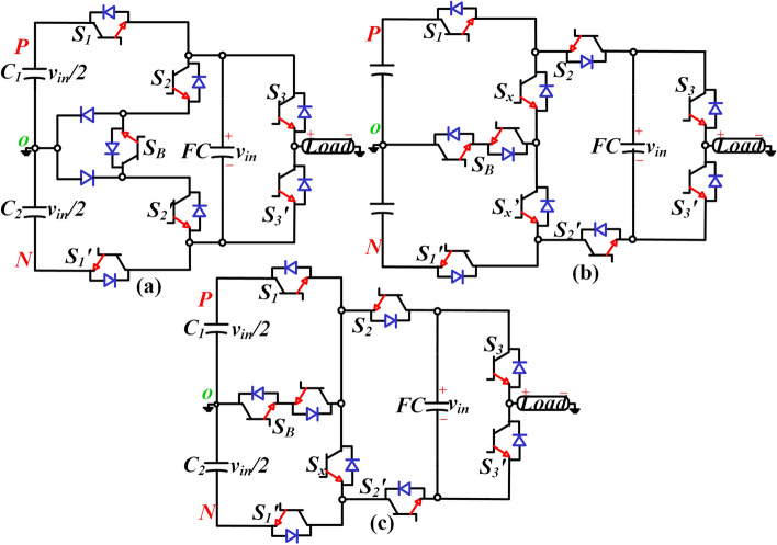
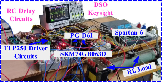
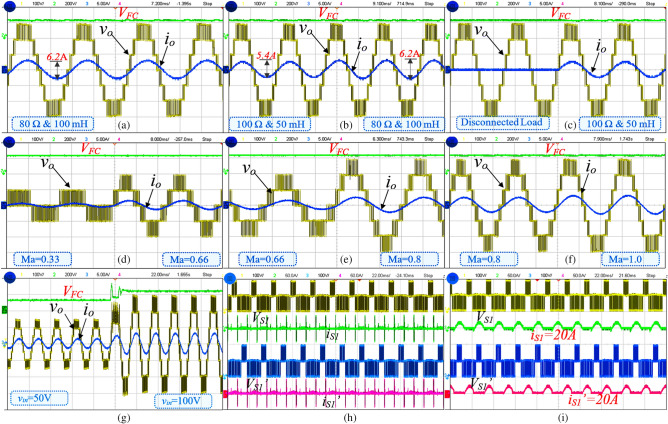
Developing of new photovoltaic inverter topologies is received more attention in the last few years. In particular, designing an active neutral-point-clamping inverter type structure is quite popular for PV applications. The output voltage is always half of the input voltage (vin), which further increases the voltage rating of dc-link capacitors in the conventional three-level ANPC. To rectify the above problem and increase the output voltage by reducing dc-link capacitors voltage rating, a new boost type seven-level ANPC inverter topology is proposed. The proposed topology consists of seven switches and one floating capacitor. The floating capacitor voltage is self-balanced, and the output voltage is 1.5 times higher than the input voltage. A detailed comparison for some power components, power loss and cost with other existing topologies are presented. Further, the proposed topology is validated in a prototype hardware setup for different load values.
© 2021. The Author(s).
Conflict of interest statement
The authors declare no competing interests.
Figures


References
-
- Hinago Y, Koizumi H. A switched-capacitor inverter using series/parallel conversion with inductive load. IEEE Trans. Ind. Electron. 2012;59(2):878–887. doi: 10.1109/TIE.2011.2158768. - DOI
-
- Babaei E, Gowgani SS. Hybrid multilevel inverter using switched capacitor units. IEEE Trans. Ind. Electron. 2014;61(9):4614–4621. doi: 10.1109/TIE.2013.2290769. - DOI
Grants and funding
LinkOut - more resources
Full Text Sources
