Review
. 2022 Feb;9(4):e2103953.
doi: 10.1002/advs.202103953. Epub 2021 Nov 18.

"Porous and Yet Dense" Electrodes for High-Volumetric-Performance Electrochemical Capacitors: Principles, Advances, and Challenges

Affiliations
Review

"Porous and Yet Dense" Electrodes for High-Volumetric-Performance Electrochemical Capacitors: Principles, Advances, and Challenges

Zhenghui Pan et al. Adv Sci (Weinh). 2022 Feb.

Abstract

With the ever-rapid miniaturization of portable, wearable electronics and Internet of Things, the volumetric performance is becoming a much more pertinent figure-of-merit than the conventionally used gravimetric parameters to evaluate the charge-storage capacity of electrochemical capacitors (ECs). Thus, it is essential to design the ECs that can store as much energy as possible within a limited space. As the most critical component in ECs, "porous and yet dense" electrodes with large ion-accessible surface area and optimal packing density are crucial to realize desired high volumetric performance, which have demonstrated to be rather challenging. In this review, the principles and fundamentals of ECs are first observed, focusing on the key understandings of the different charge storage mechanisms in porous electrodes. The recent and latest advances in high-volumetric-performance ECs, developed by the rational design and fabrication of "porous and yet dense" electrodes are then examined. Particular emphasis of discussions then concentrates on the key factors impacting the volumetric performance of porous carbon-based electrodes. Finally, the currently faced challenges, further perspectives and opportunities on those purposely engineered porous electrodes for high-volumetric-performance EC are presented, aiming at providing a set of guidelines for further design of the next-generation energy storage devices.

Keywords: electrochemical capacitors; high volumetric performance; portable and wearable electronics; “porous and yet dense” electrodes.


Conflict of interest statement

The authors declare no conflict of interest.

Figures

Figure 1
Figure 1
a) Ragone plots of traditional capacitors, electrochemical capacitors (including EDLCs, PCs, and HCs), and Li‐ion batteries. b) Global ECs market share maps according to regions (y‐axis) and years (x‐axis). Reproduced with permission.[ 16 ] Copyright 2021, Royal Society of Chemistry. c) A schematic illustration of the construction of the commercial coin cell. d) The Ragone plots for the same ECs are on a volumetric basis. Reproduced with permission.[ 17 ] Copyright 2011, American Association for the Advancement of Science (AAAS).
Figure 2
Figure 2
a) Historic timeline in development of ECs. Reproduced with permission.[ 15 ] Copyright 2020, Royal Society of Chemistry. General energy storage mechanisms and device structure of three types of EC: b) EDLC, c) PC, and d) HC.
Figure 3
Figure 3
a) The upper left panel shows the schematic representation of an EDLC using porous carbon materials as the electrode materials. The upper right panel gives the simulation EDL cell consisting of a porous electrode filled with an IL (blue: carbon atoms, red: cation, and green: anion). The bottom left panel shows the equivalent circuit of an EDLC and the bottom right panel gives a schematic representation of EDL formation of a negative electrode. b) Three different types of pseudocapacitive electrodes: under‐potential deposition, redox PC, and ion intercalation PC. c) Various types of HC and their electrode and electrolyte materials. d) CV features for different EC configurations of asymmetric devices and hybrid devices (A and B are different materials). Reproduced with permission.[ 20 ] Copyright 2019, Wiley‐VCH.
Figure 4
Figure 4
a) Effects of electrolyte on the EC performance. b) Classification of electrolytes for ECs.
Figure 5
Figure 5
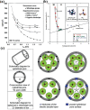
Factors influencing the volumetric performance of porous carbon‐base electrodes.
Figure 6
Figure 6
a) The C vol and C wt of previously reported carbon materials in aqueous electrolytes. Reproduced with permission.[ 10 ] Copyright 2016, Royal Society of Chemistry. b) The area‐normalized capacitance (C areal, top) and the C wt (bottom) of various types of porous carbon electrodes at the point of zero charge (PZC) versus the SSA. Reproduced with permission.[ 66a ] Copyright 2014, Nature Publishing Group. c) IUPAC classification of physisorption isotherms. d) Summary of information obtained from the different isotherms. c,d) Reproduced with permission.[ 67b ] Copyright 2015, The International Union of Pure and Applied Chemistry.
Figure 7
Figure 7
a) Relationship between the C vol (theoretical and experimental) and the pore size in aqueous electrolyte or organic electrolyte for ACs. Reproduced with permission.[ 72b ] Copyright 2006, Elsevier. b) Plot of C areal normalized by SSA for the carbons in this study and in two other studies with identical electrolytes. Reproduced with permission.[ 72c ] Copyright 2010, The Royal Society Publishing. c) Schematic diagrams of a model based on the spherical IL electrolyte ions and carbon materials with cylindrical pore surface. Reproduced with permission.[ 66b ] Copyright 2013, American Chemical Society.
Figure 8
Figure 8
a) Schematic illustration of the HGFs as a material for EC electrodes. Reproduced with permission.[ 35 ] Copyright 2014, Nature Publishing Group. b) The trade‐off relationship between electrical conductivity and pore structure.
Figure 9
Figure 9
a) Schematic diagram of the interactions between pore features with ESSA, ρ, and electrical conductivity. b) Theoretical estimation of the relation between the intersheet spacing and the ρ of graphene in a face‐to‐face arranged assembly. Reproduced with permission.[ 36 ] Copyright 2013, American Association for the Advancement of Science (AAAS).
Figure 10
Figure 10
a) Nitrogen adsorption–desorption isotherms and b) DFT pore size distributions of the porous carbons. Reproduced with permission.[ 79d ] Copyright 2010, Elsevier. c) A typical TEM image of the as‐prepared CNC annealed at 700 °C. Inset is the corresponding HRTEM image. Reproduced with permission.[ 65b ] Copyright 2017, Wiley‐VCH. d) A typical TEM image of CS15A4 material. e) The pore size distribution curves of the porous carbons. Reproduced with permission.[ 80 ] Copyright 2008, Elsevier. f) A typical SEM image of as‐prepared MEGO by microwave irradiation. Inset is the high magnification SEM image showing the crumpled MEGO sheets. Reproduced with permission.[ 81 ] Copyright 2010, Elsevier. g) Schematic showing the microwave exfoliation of GO and the following chemical activation of MEGO with KOH that creates pores while retaining high electrical conductivity, and the corresponding SEM and TEM images of the a‐MEGO. Reproduced with permission.[ 82 ] Copyright 2011, American Association for the Advancement of Science (AAAS). h) The pore size distributions of uncompressed and compressed a‐MEGO‐based electrodes. Reproduced with permission.[ 65a ] Copyright 2013, Elsevier.
Figure 11
Figure 11
a) Schematic of a scalable synthesis of the h‐Graphene sheets and their corresponding SEM, TEM, and pore size distribution statistic. Reproduced with permission.[ 65d ] Copyright 2014, American Chemical Society. b) Schematic for fabricating the ac‐Gr/SWCNT hybrid nanostructure. Reproduced with permission.[ 90 ] Copyright 2015, American Chemical Society. c) Schematic of the formation of graphene‐based 3D porous macroforms with different drying process and the SEM images of the resultant PGM and HPGM. Reproduced with permission.[ 91 ] Copyright 2013, Nature Publishing Group. d) A photograph and SEM images of EM‐CCG film. Reproduced with permission.[ 36 ] Copyright 2013, American Association for the Advancement of Science (AAAS).
Figure 12
Figure 12
a) Electrode fabrication and characterization of SWCNT electrode. Reproduced with permission.[ 92 ] Copyright 2010, Wiley‐VCH. b) SEM image of SWCNT‐forest structural collapse from a single drop of liquid. Schematic diagram of c) the collapse of the aligned low‐density as‐grown forest (above) to the highly densely packed SWCNT solid (below), and d) the model comparing the ion diffusion for AC and the SWCNT solid material. Reproduced with permission.[ 94 ] Copyright 2006, Nature Publishing Group. e) SEM and TEM images of the macroporous cores of the HPGC material. f) Schematic representation of the 3D hierarchical porous texture. Reproduced with permission.[ 95 ] Copyright 2008, Wiley‐VCH. g) “Egg‐box” model of calcium alginate in brown seaweed and its derived surface mesopore engineering (SME) process for nanoporous carbons. h,i) Pore characterization of seaweed‐derived carbon materials with SME (AHPC) and without SME (AC) treatment. Reproduced with permission.[ 96 ] Copyright 2015, American Chemical Society.
Figure 13
Figure 13
a) Overall picture of wood‐based structures for electrochemical energy storage application. Reproduced with permission.[ 78b ] Copyright 2021, Wiley‐VCH. b) Graphical illustration of the design concept and construction process of the all‐wood‐structured supercapacitor. Reproduced with permission.[ 77a ] Copyright 2017, Royal Society of Chemistry. c) Schematic illustration of the DFCs fabricated from a modified porocellulose, obtained via a one‐pot chemical treatment of natural wood. Reproduced with permission.[ 100a ] Copyright 2020, Royal Society of Chemistry.
Figure 14
Figure 14
a) Schematic representation of the electrochemical stability range of water and potential windows versus SHE for different PC materials in an aqueous electrolyte. Reproduced with permission.[ 21 ] Copyright 2018, American Chemical Society. b) Schematic showing the synthesis of 2D m‐MnO2 nanosheets. c,d) TEM images of 2D m‐MnO2 nanosheets. Reproduced with permission.[ 104 ] Copyright 2019, Elsevier. e,f) SEM and TEM images of porous yet densely stacked MnO2@graphene composites. Reproduced with permission.[ 105 ] Copyright 2016, Wiley‐VCH. g) Illustration of preparing the MnO2@CNTs@3DGA hybrid film. The inset is the SEM image of MnO2@CNTs @3DGA hybrid. Reproduced with permission.[ 6a ] Copyright 2017, Wiley‐VCH.
Figure 15
Figure 15
a) Schematic showing the crystal structure of MoS2. TEM images of the mp‐MoS2 b) before and c) after cycling. Reproduced with permission.[ 116 ] Copyright 2016, Wiley‐VCH. d) TEM image of mesoporous α‐MoO3 with highly oriented crystalline walls. Reproduced with permission.[ 117 ] Copyright 2010, Nature Publishing Group. e) Schematic explanation of the high‐performance mesoporous WO3− x electrode, and TEM image of mesoporous WO3− x . Reproduced with permission.[ 118 ] Copyright 2011, Royal Society of Chemistry.
Figure 16
Figure 16
a,b) SEM images of the PANI film deposited by pulse galvanostatic method in a reverse micelle electrolyte. Reproduced with permission.[ 125 ] Copyright 2011, Royal Society of Chemistry. c) Schematic representation of the microstructure and energy storage characteristics of the PANI/CNT composite. Reproduced with permission.[ 124 ] Copyright 2008, Elsevier. d) Fabrication and characterization of compact PANI‐CCG films. Reproduced with permission.[ 37 ] Copyright 2016, Wiley‐VCH. e) Comparison of the volumetric and gravimetric capacitances of the NFHG/PANI film with other reported materials. Reproduced with permission.[ 121c] Copyright 2021, Springer. f) Schematic illustration of fabricating PHCFs. Reproduced with permission.[ 123 ] Copyright 2018, Royal Society of Chemistry.
Figure 17
Figure 17
a) Schematic illustration of MXene structure. Reproduced with permission.[ 128 ] Copyright 2017, Nature Publishing Group. b) SEM image of a binder‐free intercalated Ti3C2T x film electrode. Reproduced with permission.[ 129 ] Copyright 2019, Elsevier. c) Cross‐sectional SEM image of the 4 and 20 µm clay‐like additive‐free Ti3C2T x films. d) Comparison of rate performance of this work and previously reported MXene films. Reproduced with permission.[ 65g ] Copyright 2014, Nature Publishing Group. e) Cross‐sectional SEM image of macroporous‐templated Ti3C2T x film. Reproduced with permission.[ 128 ] Copyright 2017, Nature Publishing Group. Cross‐sectional SEM images of f) 3D‐Ti3C2T x ‐film and g) aerogel. h) The BET results of Ti3C2T x ‐film, 3D‐Ti3C2T x ‐film, and aerogel. Reproduced with permission.[ 131 ] Copyright 2019, Elsevier.
Figure 18
Figure 18
a,b) SEM image of freestanding and porous MXene microlattice. Reproduced with permission.[ 135 ] Copyright 2019, Wiley‐VCH. c) Schematic drawing demonstrating the 3D printing of MCs with interdigital architectures. Reproduced with permission.[ 136 ] Copyright 2020, American Chemical Society. d,e) Cross‐sectional SEM images of the nanoporous MXene film. Reproduced with permission.[ 137 ] Copyright 2018, Royal Society of Chemistry. f) Schematic showing the preparation of the sandwich‐like CNT@MXene films and their digital photographs. Reproduced with permission.[ 142 ] Copyright 2015, Wiley‐VCH. g) Schematic illustration for the synthesis of the rGO@MXene hybrids. h1) Cross‐sectional SEM of rGO@MXene hybrid film. h2) TEM images of rGO@MXene hybrids. i) XRD patterns of the prepared MXene and rGO@MXene hybrids. Reproduced with permission.[ 143 ] Copyright 2017, Wiley‐VCH.

Similar articles

Cited by

References

    1. Tarascon J. M., Armand M., Nature 2001, 414, 359. - PubMed
    1. a) Pan Z., Liu X., Yang J., Li X., Liu Z., Loh X., Wang J., Adv. Energy Mater. 2021, 11, 2100608;
    2. b) Pan Z., Yang J., Jiang J., Qiu Y., Wang J., Mater. Today Energy 2020, 18, 100523;
    3. c) Zhong Y., Lu Y., Pan Z., Yang J., Du G., Chen J., Zhang Q., Zhou H., Wang J., Wang C., Li W., Adv. Funct. Mater. 2021, 31, 2009853;
    4. d) Qiu Y., Pan Z., Chen H., Ye D., Guo L., Fan Z., Yang S., Sci. Bull. 2019, 64, 1348; - PubMed
    5. e) Zeng Y., Zhang X., Qin R., Liu X., Fang P., Zheng D., Tong Y., Lu X., Adv. Mater. 2019, 31, 1903675. - PubMed
    1. Sun H., Mei L., Liang J., Zhao Z., Lee C., Fei H., Ding M., Lau J., Li M., Wang C., Xu X., Hao G., Papandrea B., Shakir I., Dunn B., Huang Y., Duan X., Science 2017, 356, 599. - PubMed
    1. a) Chen M., Pan Z., Jin X., Chen Z., Zhong Y., Wang X., Qiu Y., Xu M., Li W., Zhang Y., J. Mater. Chem. A 2019, 7, 4494;
    2. b) Zhong Y., Li B., Li S., Xu S., Pan Z., Huang Q., Xing L., Wang C., Li W., Nano‐Micro Lett. 2018, 10, 56; - PMC - PubMed
    3. c) Yang J., Liu M., Wei Z., Pan Z., Qiu Y., Ye F., Yang Y., Zhao X., Sheng L., Zhang Y., Electrochim. Acta 2016, 211, 671;
    4. d) Wang X., Pan Z., Yang J., Lyu Z., Zhong Y., Zhou G., Qiu Y., Zhang Y., Wang J., Li W., Energy Storage Mater. 2019, 22, 179;
    5. e) Dunn B., Kamath H., Tarascon J. M., Science 2011, 334, 928. - PubMed
    1. a) Simon P., Gogotsi Y., Dunn B., Science 2014, 343, 1210; - PubMed
    2. b) Yin J., Zhang W., Alhebshi N. A., Salah N., Alshareef H. N., Small Methods 2020, 4, 1900853;
    3. c) Lai F., Yang C., Lian R., Chu K., Qin J., Zong W., Rao D., Hofkens J., Lu X., Liu T., Adv. Mater. 2020, 32, 2002474; - PubMed
    4. d) Lv T., Liu M., Zhu D., Gan L., Chen T., Adv. Mater. 2018, 30, 1705489; - PubMed
    5. e) Luo H., Kaneti Y., Ai Y., Wu Y., Wei F., Fu J., Cheng J., Jing C., Yuliarto B., Eguchi M., Na J., Yamauchi Y., Liu S., Adv. Mater. 2021, 33, 2007318; - PubMed
    6. f) Yan Y., Chen G., She P., Zhong G., Yan W., Guan B., Yamauchi Y., Adv. Mater. 2020, 32, 2004654; - PubMed
    7. g) He Y., Zhuang X., Lei C., Lei L., Hou Y., Mai Y., Feng X., Nano Today 2019, 24, 103.

LinkOut - more resources