. 2021 Nov 16;12(11):1408.
doi: 10.3390/mi12111408.

Parametric Study of Jet/Droplet Formation Process during LIFT Printing of Living Cell-Laden Bioink

Affiliations

Parametric Study of Jet/Droplet Formation Process during LIFT Printing of Living Cell-Laden Bioink

Christina Kryou et al. Micromachines (Basel). .

Abstract

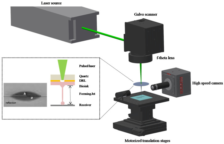
Bioprinting offers great potential for the fabrication of three-dimensional living tissues by the precise layer-by-layer printing of biological materials, including living cells and cell-laden hydrogels. The laser-induced forward transfer (LIFT) of cell-laden bioinks is one of the most promising laser-printing technologies enabling biofabrication. However, for it to be a viable bioprinting technology, bioink printability must be carefully examined. In this study, we used a time-resolved imaging system to study the cell-laden bioink droplet formation process in terms of the droplet size, velocity, and traveling distance. For this purpose, the bioinks were prepared using breast cancer cells with different cell concentrations to evaluate the effect of the cell concentration on the droplet formation process and the survival of the cells after printing. These bioinks were compared with cell-free bioinks under the same printing conditions to understand the effect of the particle physical properties on the droplet formation procedure. The morphology of the printed droplets indicated that it is possible to print uniform droplets for a wide range of cell concentrations. Overall, it is concluded that the laser fluence and the distance of the donor-receiver substrates play an important role in the printing impingement type; consequently, a careful adjustment of these parameters can lead to high-quality printing.

Keywords: cell-laden bioink; distance; droplet/jet impingement; laser fluence; laser-induced forward transfer; time-resolved imaging.


Conflict of interest statement

The authors declare no conflict of interest.

Figures

Figure 1
Figure 1
Schematic of LIFT setup.
Figure 2
Figure 2
Time-resolved images of the LIFT printed cell-free bioinks at different laser fluences: (a) Bioink A; (b) Bioink B. In every image, the laser beam is impinging the donor substrate from above, with the receiver substrate being placed at a distance of 500 μm with respect to the donor substrate. Scale bar: 100 μm.
Figure 3
Figure 3
Time-resolved images of the LIFT-printed cell-laden bioinks at different laser fluences. (a) Bioink C; (b) Bioink D; (c) Bioink E; (d) Bioink F; (e) Bioink G. In every image, the laser beam is impinging the donor substrate from above, with the receiver substrate being placed at a distance of 500 μm with respect to the donor substrate. Scale bar: 100 μm.
Figure 3
Figure 3
Time-resolved images of the LIFT-printed cell-laden bioinks at different laser fluences. (a) Bioink C; (b) Bioink D; (c) Bioink E; (d) Bioink F; (e) Bioink G. In every image, the laser beam is impinging the donor substrate from above, with the receiver substrate being placed at a distance of 500 μm with respect to the donor substrate. Scale bar: 100 μm.
Figure 4
Figure 4
Schematic of jet formation (and respective experimental results of Bioink F) as a function of different distances between the donor–receiver substrate: (a) Subthreshold regime, morphological feature of a forming jet from 7.8–54.6 μs, during printing of Bioink F, under 200 mJ/cm2 and a 500 μm distance between the donor–receiver substrate; (b) Well-defined printing regime where: (i) Droplet impingement; (A1) morphological feature of a forming jet at 327 μs during printing of Bioink F at 500 mJ/cm2 and a 1500 μm distance between the donor–receiver substrate; and (A2) morphological feature of a forming jet at 273 μsduring printing of Bioink F at 500 mJ/cm2, with a 2000 μm distance between the donor–receiver substrate; (c) Plume regime; (C1) morphological feature of a forming jet at 46.8μs during printing of Bioink F at 900 mJ/cm2 and a 500 μm distance between the donor–receiver substrate.
Figure 5
Figure 5
Droplet diameter as a function of cell concentration at 500 mJ/cm2. Error bars depict STDEV, n = 4 droplets per condition.
Figure 6
Figure 6
(a) Average jet velocities of all bioinks. Error bars depict STDEV, n= 4 droplets per condition; (b) Second jet length vs. time for all bioinks at 500 mJ/cm2. Bottom inlet, first jet length vs. time for all bioinks at 500 mJ/cm2.
Figure 7
Figure 7
Microscopy images of the printed cell-laden bioinks at 500 mJ/cm2: (a) Bioink C; (b) Bioink D; (c) Bioink E; and (d) Bioink F, on the gelatin-coated glass slide 15 min after printing. To determine the cellular survival after printing, cells were stained with Hoechst 33,258 and PI (red PI staining indicates dead cells, while all printed cells are displayed in blue). Scale bar: 100 μm.
Figure 8
Figure 8
(a) LIFT-printed droplet diameters as a function of laser fluence; (b) LIFT-printed volume as a function of laser fluence.
Figure 9
Figure 9
Time-resolved images of the LIFT Bioink F as a function of distance between the donor–receiver substrate: (a) 0.5 mm; (b) 1.0 mm; (c) 1.5 mm; and (d) 2.0 mm.Scale bar: 100 μm.
Figure 10
Figure 10
(a) LIFT-printed droplet diameter; and (b) LIFT-printed volume as a function of distance, at 500 mJ/cm2. Error bars depict STDEV, n = 4 droplets per condition.

References

    1. Ringeisen B.R., Pirlo R.K., Wu P.K., Boland T., Huang Y., Sun W., Hamid Q., Chrisey D.B. Cell and organ printing turns 15: Diverse research to commercial transitions. MRS Bull. 2013;38:834–843. doi: 10.1557/mrs.2013.209. - DOI
    1. Nakamura M., Iwanaga S., Henmi C., Arai K., Nishiyama Y. Biomatrices and biomaterials for future developments of bioprinting and biofabrication. Biofabrication. 2010;2:014110. doi: 10.1088/1758-5082/2/1/014110. - DOI - PubMed
    1. Lee H., Young W.K., Miji Y., Kim S.H., Kim G.H. Recent cell printing systems for tissue engineering. Int. J. Bioprinting. 2017;3:27–41. doi: 10.18063/IJB.2017.01.004. - DOI - PMC - PubMed
    1. Christensen K., Xu C., Chai W., Zhang Z., Fu J., Huang Y. Freeform inkjet printing of cellular structures with bifurcations. Biotechnol. Bioeng. 2015;112:1047–1055. doi: 10.1002/bit.25501. - DOI - PubMed
    1. Kryou C., Leva V., Chatzipetrou M., Zergioti I. Bioprinting for Liver Transplantation. Bioengineering. 2019;6:95. doi: 10.3390/bioengineering6040095. - DOI - PMC - PubMed

LinkOut - more resources