

Towards Autonomous Drone Racing without GPU Using an OAK-D Smart Camera
- PMID: 34833511
- PMCID: PMC8620925
- DOI: 10.3390/s21227436
Towards Autonomous Drone Racing without GPU Using an OAK-D Smart Camera
Abstract
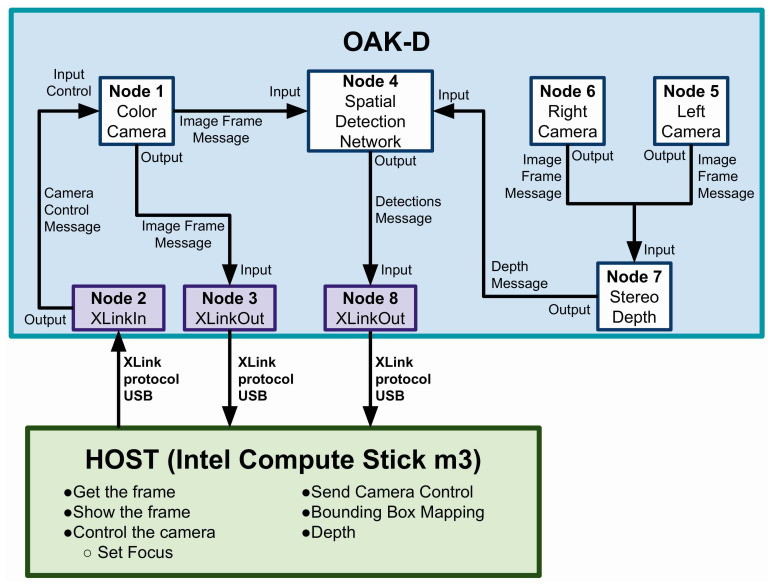
Recent advances have shown for the first time that it is possible to beat a human with an autonomous drone in a drone race. However, this solution relies heavily on external sensors, specifically on the use of a motion capture system. Thus, a truly autonomous solution demands performing computationally intensive tasks such as gate detection, drone localisation, and state estimation. To this end, other solutions rely on specialised hardware such as graphics processing units (GPUs) whose onboard hardware versions are not as powerful as those available for desktop and server computers. An alternative is to combine specialised hardware with smart sensors capable of processing specific tasks on the chip, alleviating the need for the onboard processor to perform these computations. Motivated by this, we present the initial results of adapting a novel smart camera, known as the OpenCV AI Kit or OAK-D, as part of a solution for the ADR running entirely on board. This smart camera performs neural inference on the chip that does not use a GPU. It can also perform depth estimation with a stereo rig and run neural network models using images from a 4K colour camera as the input. Additionally, seeking to limit the payload to 200 g, we present a new 3D-printed design of the camera's back case, reducing the original weight 40%, thus enabling the drone to carry it in tandem with a host onboard computer, the Intel Stick compute, where we run a controller based on gate detection. The latter is performed with a neural model running on an OAK-D at an operation frequency of 40 Hz, enabling the drone to fly at a speed of 2 m/s. We deem these initial results promising toward the development of a truly autonomous solution that will run intensive computational tasks fully on board.
Keywords: Autonomous Drone Racing; CNN; OAK-D; deep learning; smart camera.
Conflict of interest statement
The authors declare no conflict of interest.
Figures


Similar articles
-
DeepPilot: A CNN for Autonomous Drone Racing.Sensors (Basel). 2020 Aug 13;20(16):4524. doi: 10.3390/s20164524. Sensors (Basel). 2020. PMID: 32823503 Free PMC article.
-
Visual attention prediction improves performance of autonomous drone racing agents.PLoS One. 2022 Mar 1;17(3):e0264471. doi: 10.1371/journal.pone.0264471. eCollection 2022. PLoS One. 2022. PMID: 35231038 Free PMC article.
-
Champion-level drone racing using deep reinforcement learning.Nature. 2023 Aug;620(7976):982-987. doi: 10.1038/s41586-023-06419-4. Epub 2023 Aug 30. Nature. 2023. PMID: 37648758 Free PMC article.
-
Advancements in Algorithms and Neuromorphic Hardware for Spiking Neural Networks.Neural Comput. 2022 May 19;34(6):1289-1328. doi: 10.1162/neco_a_01499. Neural Comput. 2022. PMID: 35534005 Review.
-
Overview of Spiking Neural Network Learning Approaches and Their Computational Complexities.Sensors (Basel). 2023 Mar 11;23(6):3037. doi: 10.3390/s23063037. Sensors (Basel). 2023. PMID: 36991750 Free PMC article. Review.
References
-
- Jung S., Cho S., Lee D., Lee H., Shim D.H. A direct visual servoing-based framework for the 2016 IROS Autonomous Drone Racing Challenge. J. Field Robot. 2018;35:146–166. doi: 10.1002/rob.21743. - DOI
-
- Moon H., Martinez-Carranza J., Cieslewski T., Faessler M., Falanga D., Simovic A., Scaramuzza D., Li S., Ozo M., De Wagter C. Challenges and implemented technologies used in autonomous drone racing. Intell. Serv. Robot. 2019;12:137–148. doi: 10.1007/s11370-018-00271-6. - DOI
-
- Jung S., Hwang S., Shin H., Shim D.H. Perception, guidance, and navigation for indoor autonomous drone racing using deep learning. IEEE Robot. Autom. Lett. 2018;3:2539–2544. doi: 10.1109/LRA.2018.2808368. - DOI
-
- Kaufmann E., Gehrig M., Foehn P., Ranftl R., Dosovitskiy A., Koltun V., Scaramuzza D. Beauty and the beast: Optimal methods meet learning for drone racing; Proceedings of the 2019 International Conference on Robotics and Automation (ICRA); Montreal, QC, Canada. 20–24 May 2019; pp. 690–696.
-
- Cocoma-Ortega J.A., Martinez-Carranza J. A compact CNN approach for drone localisation in autonomous drone racing. J. Real-Time Image Process. 2021:1–14. doi: 10.1007/s11554-021-01162-3. - DOI
MeSH terms
LinkOut - more resources
Full Text Sources
Research Materials
