. 2021 Dec 9;184(25):6052-6066.e18.
doi: 10.1016/j.cell.2021.11.010. Epub 2021 Nov 30.

The epitope arrangement on flavivirus particles contributes to Mab C10's extraordinary neutralization breadth across Zika and dengue viruses

Affiliations

The epitope arrangement on flavivirus particles contributes to Mab C10's extraordinary neutralization breadth across Zika and dengue viruses

Arvind Sharma et al. Cell. .

Abstract

The human monoclonal antibody C10 exhibits extraordinary cross-reactivity, potently neutralizing Zika virus (ZIKV) and the four serotypes of dengue virus (DENV1-DENV4). Here we describe a comparative structure-function analysis of C10 bound to the envelope (E) protein dimers of the five viruses it neutralizes. We demonstrate that the C10 Fab has high affinity for ZIKV and DENV1 but not for DENV2, DENV3, and DENV4. We further show that the C10 interaction with the latter viruses requires an E protein conformational landscape that limits binding to only one of the three independent epitopes per virion. This limited affinity is nevertheless counterbalanced by the particle's icosahedral organization, which allows two different dimers to be reached by both Fab arms of a C10 immunoglobulin. The epitopes' geometric distribution thus confers C10 its exceptional neutralization breadth. Our results highlight the importance not only of paratope/epitope complementarity but also the topological distribution for epitope-focused vaccine design.

Keywords: Dengue virus; Flaviviruses; X-ray crystallography; Zika virus; broadly neutralizing antibodies; cryo-EM; vaccine design.


Conflict of interest statement

Declaration of interests F.A.R. is a board member and shareholder of EureKARE and MELETIUS Therapeutics. G.R.S. is member of the GSK Vaccines Scientific Advisory Board and a founding shareholder of RQ Biotechnology. G.R.S., F.A.R., P.G.-C., M.-C.V, A.R., S.D., and J.M. are authors in a patent concerning EDE mAbs, including C8 and C10:US20180037611A1 (2018): Anti-dengue vaccines and antibodies. G.R.S., F.A.R., M.-C.V., A.R., and J.M. are authors of patent CA3066488A1 (2017): Neutralising antibody against dengue for use in a method of prevention and/or treatment.

Figures

None
Graphical abstract
Figure 1
Figure 1
Virus-dependent bivalent versus monovalent C10 neutralization differences (A) The DENV2 sE dimer color-coded by domain with the C10 footprint outlined (heavy chain in magenta, light chain in cyan) (PDB: 4UT9). A green oval at the center marks the molecular 2-fold axis. The sE protomer contributing the fusion loop (FL; orange) or domain III (blue) to the epitope are dubbed “reference” or “opposite” subunit, respectively. (B) The flavivirus mature virion displayed in surface representation with selected icosahedral symmetry axes shown as full green symbols: 2-fold (I2, oval), 3-fold (I3, triangle), and 5-fold (I5, pentagon). 90 E dimers are arranged as 30 “rafts” (green outlines) made of three E dimers. The central, I2 dimer (white) is flanked by two L2 dimers, (light/dark gray) formed about local 2-fold axes (open green ovals). The location of the C10 epitopes is outlined in magenta in the front raft, labeled 2f, 3f, and 5f. (C) Bivalent versus monovalent C10 binding and neutralization. Top: cartoon of IgG1, F(ab’)2, and Fab molecules. Bottom: ELISA titration curves and the estimated apparent dissociation constant (KD) (left panels) and neutralization curves with the 50% focus reduction neutralization titer (FRNT 50%) measured on Vero cells (right panels) for ZIKV and DENV1–DENV4 grown in insect cells. Data are from three independent experiments.
Figure S1
Figure S1
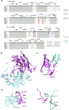
Sequence analysis of C10 and interacting residues of the paratope, related to Figure 2 (A) Amino acid sequence of the C10 heavy (i) and light chains (ii) numbered according to the Kabat convention with the CDRs in white background. The CDRs in the IGMT convention are indicated by a blue line over the sequence. Somatic mutations are marked with red fonts, with the germline aa indicated immediately above. Residues arising from nucleotide insertions at the recombination sites (“N” residues) are in green. The five rows below the sequences mark antigen contacting residues as observed in the corresponding X-ray structures of sE in complex with C10 (see colored key at the bottom right inset). Boxed are key residues at the interface of heavy and light chains important for maintaining the conformational integrity of the paratope. The germline alleles are quoted on the right. (B) The C10 paratope as observed in the X-ray structure of the complex with ZIKV sE complex at 2.1 Å resolution viewed from the antigen and with important residues labeled (magenta, heavy chain; cyan, light chain). (C) HCDR3 residue YH100C (black arrow) and its interactions at the VH/VL interface to allow the correct exposure of paratope residues at the tip of the HCDR3. This structural role is reflected in the strong phenotype of the YH100C mutant. (D) LCDR1 residue YL32 and its structuring role at the heavy/light chain interface. (E) The LCDR2 TL52 side chain makes a bond with the backbone carbonyl group of DL50, which in turn packs against residue LH100H of the HCDR3. The strong effect of the TL52A mutation - like that of YL32A (Figure 2B), likely reflects conformational disruption of both, HCDR3 and LCDR1 loops.
Figure 2
Figure 2
Robustness of the C10 paratope to point mutations Binding and neutralization ratios of EDE1 C10 mutants are color-coded as the ratio to wild-type according to the key. The C10 residues mutated are presented in Kabat numbering, with light and heavy chains marked with black and magenta font, respectively, highlighting in bold those that most severely affect neutralization breadth. Blue arrows indicate heavy/light-chain interface residues. (A) Germline reversion mutants (see also Figure S1A). (B) Alanine scanning of the paratope. See also Table S1.
Figure S2
Figure S2
Amino-acid sequence alignment of sE from ZIKV and DENV1-DENV4 and their X-ray structures in complex with C10, related to Figure 3 (A) Amino acid sequence alignment of sE of ZIKV and DENV1-4. A black background highlights strict aa conservation. Residues contacted by C10 in each of the complexes are indicated in a magenta (heavy chain) or cyan (light chain) background. The domain organization (domain1 red, domain II yellow, fusion peptide orange and domain III in blue) and the secondary structure elements are indicated together with their labels above the sequences. A bar ramp-colored from blue to red indicates the segment highlighted in Figure 6A. (B) X-ray structures of ZIKV sE in complex with C10 Fab and of DENV1, DENV3 and DENV4 in complex with C10 scFv. The resolution and crystallographic statistic are quoted, and are provided in detail in Table S2. The 2-fold molecular symmetry of the ZIKV and DENV1 complexes, coincident with a 2-fold crystallographic axis, is drawn in green. The DENV4 and DENV3 complex were not 2-fold symmetric, and displayed significant variation at the antibody/antigen interface. (C) Some sE conformations observed in the complexes with C10 are incompatible with its interactions on virions. The left panel shows an alignment of the X-ray structures on the domain II tip of the E protein on the ZIKV virion at 3.1Å resolution (PDB: 6CO8). The view corresponds to Figure 3A rotated by 180 degrees about a vertical axis. The circle marks the location of the inset shown in the right panels, color-coded according to the rightmost panel. (D) X-ray structure of the DENV4 (sE/C10)2 dimer site 2 (in magenta) aligned on the domain II tip of the Zika virion cryo-EM structure (6CO8), showing that the ij hairpin conformation in the crystal would clash with protein M (in orange), as highlighted in the right inset (black arrow). The E stem (the region C-terminal to domain III that connects to the trans-membrane anchor, and absent in sE) is displayed in gray. (E) X-ray structure of DENV3 sE L107C/ S311C double cysteine mutant (Rouvinski et al., 2017) bound to Fab C8. The crystallographic 2-fold axis is shown in green. The inset shows the engineered disulfide and 2FoFc map density at 1.2 σ. (F-G) X-ray structures of unbound DENV1 sE and DENV3 sE (see Table S2).
Figure 3
Figure 3
X-ray structures of C10 bound to ZIKV and DENV1–DENV4 sE (A) The ten snapshots of C10 (gray) bound to sE (color-coded as in the key) superposed on the C10V Cα atoms. The second antibody bound per sE dimer is not displayed for clarity (see also Figure S2). (B) The RMSD of the C10V main-chain atoms calculated upon the alignment shown in (A), color-coded on the backbone ribbon (left panel) and on all atoms shown as sticks (right panel) according to the color bar key. Black or blue arrows point to paratope residues displaying high or low side-chain rotamer variability, respectively. Light- and heavy-chain residues are labeled in cyan and magenta, respectively. (C) The C10 core epitope and open book representation of the ZIKV/C10 complex. The mean RMSD of backbone atoms calculated upon the superposition shown in (A) is color coded on a semi-transparent surface. The C10 CDRs and selected sE elements are labeled.
Figure 4
Figure 4
Cryo-EM structure of the DENV2 virion bound to scFv (A) Cryo-EM density map colored according to particle radius as in the key, adjusted to highlight in yellow densities projecting beyond a radius of ∼235 Å, which encompasses most of the E protein layer (gray). The projections at higher radii correspond to the scFvs together with the Asn67-linked glycan on the L2 dimers and to domain III and the Asn67- and Asn153-linked glycans on the I2 dimer. Domain III projects out farther in the I2 than in the L2 dimers. The epitopes are labeled as in Figure 1B, and a similar green outline highlights one raft. The right panel shows the model built into the cryo-EM density of the left panel, with the E protein colored as in Figure 1B and shown in surface representation, with the attached glycans displayed as red spheres. The bound scFv at the 3f and 5f epitopes is shown as yellow ribbons. (B) C10 footprint on the virion. The E subunits are colored white/gray as in Figure 1B, with the C10 footprint colored by E domains as in Figure 1A. Within the outlined raft, three independent E polypeptides are labeled A, B, and C, and the I2 related counterparts are labeled A’, B’, and C’, with I2 dimers made by subunit AA’ and L2 by BC and B’C’. The top left I5 axis relates subunits A, B, and C to A’’’, B’’’, and C’’’ and A’, B’, and C’ to A’’, B’’, and C’’ of the adjacent raft. The C10 footprint on the contacting L2 dimer includes inter-raft contacts to domain I of C’’’ and domain III of A’’ at the 5f epitope and to domain II of A at the 3f site.
Figure S3
Figure S3
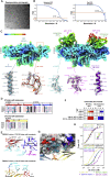
The cryo-EM structure of the DENV2 virion bound to C10, related to Figure 4 (A) Representative cryo-micrograph showing a field of DENV2 virions in complex with C10 scFv, from which the cryo-EM map was derived. (B) Fourier shell correlation function indicating an overall resolution of about 3.7 Å. Which was extended to 3.3Å upon using a mask (see Stat Methods). (C) Top panels: the final cryo-EM density around the I2 (left) and L2 (right) dimer colored according to local resolution as estimated by ResMap (Kucukelbir et al., 2014). Bottom panels: representative densities of the final model within cryo-EM density. From left to right: C-terminal TM helix in E; 150 loop tranced in the I2 dimer; LCDR3 as traced in the scFv bound to the 3f site; HCDR3 traced at the same site; and C-terminal TM helix of M (D) Portion of the aa sequence alignment of the E protein showing the conservation of the residues contacted at the epitope extensions on the virion. Full vertical arrows below the alignment indicate residues observed in contact with C10 in both in the ZIKV and DENV2 cryo-EM structures. Empty arrows mark residues contacted by C10 either in ZIKV or DENV2 virion. Residues forming epitope extensions are highlighted in a magenta (heavy chain) or cyan (light chain) background. (E) C10 contacts with the adjacent raft at the 5f (top panel) and at the 3f (bottom panel) epitope in the DENV2 virion. Only the L2 and I2 dimers of the adjacent raft are displayed as ribbons, and the C10 loops making contacts are shown as sticks color coded by atom type with carbon atoms cyan and magenta for light and heavy chain, respectively. The residues making lateral contacts were identified using a distance cutoff of 5 Å. (F) Alanine scanning of C10 residues contacting epitope extensions on the virion. The binding and neutralization ratios for C10 mutants bearing alanine at the indicated positions is displayed as in Figure 2 (related to Table S1). (G) Close-up of the C10 contact with the adjacent raft (labeled C’’’-DI and A’’’-DIII, see Figure 4B) at the 5f site. The E dimers of the adjacent raft are shown in surface representation, and the E dimer on which C10 is bound is shown as ribbons colored coded by domains as in Figure 1A. For clarity, only the C10 loops in contact with the adjacent dimers are shown, in cyan and magenta for light and heavy chain, respectively. The cryo-EM density for the displayed C10 residues is represented in a cyan mesh. The dotted black line shows a polar bond of the KL66 side chain with the backbone of LCDR1 residue FL30. (H) Steady state binding of WT IgG1 C10 and the KL66A mutants to the recombinant sE dimers and the measured KD values. The color code is indicated below the Figure. The C10 KL66A mutant also affected binding to the isolated sE dimers, indicating that the effect of this mutation is due to its role in structuring the paratope and not because of the inter-raft contact.
Figure S4
Figure S4
Interactions of the C10 CDRs with E in the various complexes analyzed, related to Figure 5 The two insets in the top row display two representative complexes displayed below: a fully symmetric (sE/C10)2 dimer with two identical C10 binding sites (left), and an asymmetrical (sE/C10)2 dimer with two different binding sites. Accordingly, only one site (site 0, symmetric dimers) and both sites (sites 1 and 2, asymmetric dimers) are enlarged in the panels below. For ease of comparison, the site 2 is shown in the closeup after a 180° rotation about the vertical axes (as indicated by the symbol). The coloring of the E domains in the two protomers is also used as a guide: bright and washed colors match those in the inset. The C10 variable region is shown as ribbons with the heavy and light chains colored magenta and cyan, respectively. The structures shown in all the other panels were aligned on C10V and, except for the two insets, only the C10 CDRs are shown for clarity. The paratope residues making contact are shown as sticks. Paratope residues that make contact in some structures, but not in the panel being displayed, are labeled in fainted font color, for instance SL56 or DH100B in panel A. The various panels show that the HCDR3 protrusion adapts differently to the various complexes, and often induces disorder in the ij and kl hairpin region in the asymmetric complexes (white arrows), and affect the sE dimer differently in both binding sites in the sE dimer. The most variable is the conformation of the WH100D, at the very tip of the HCDR3.
Figure 5
Figure 5
C10 docking on virions and comparison with soluble sE dimers (A) The five cryo-EM C10/E snapshots displayed upon alignment on C10V bound to the 2f, 3f, and 5f epitopes on the ZIKV virion (PDB: 5H37) and to the 3f and 5f epitopes of the DENV2 virion (i.e., equivalent to Figure 3A with the 10 X-ray C10/sE snapshots) (Table S4). (B) C10 docking axes (defined as the axis of the transformation relating the core β sandwiches of the C10 VH and VL domains). Instead of aligning on the antibody, each structural snapshot was aligned to the core epitope (defined in Figure 3C) of the reference structure (ZIKV sE/Fab C10 at 2.1-Å resolution, termed ZIKV sE), and the docking axis obtained after this alignment is displayed (Table S5). In the three panels, ZIKV sE is shown in surface representation without the bound C10 Fab; only the C10 docking axis determined on this structure is shown in yellow, labeled “0.” A pink star to the right marks the location of the Asn67-linked glycan, present only on DENVs. Overlapped onto it are the docking axes determined for the 5 cryo-EM snapshots of (A) in the left panel, those determined for the 10 X-ray snapshots of sE/C10 complexes displayed in Figure 3A in the center panel, and the docking axes for Mab C8 in five available X-ray snapshots in the right panel. The docking axes in symmetric complexes are labeled 0 and the asymmetric ones 1 and 2 (and 1’ and 2′ when there are two dimers in the AU in the crystal) in the respective colors. 0 and 0’ in the third panel correspond to the X-ray structure of the ZIKV sE/C8 complex (PDB: 5LBS), which had two crystallographic half dimers in the AU. (C) Side view of C10V and C8V in the same orientation, with the CDRs highlighted. Note the bulkier projection of the C10 HCDR3.
Figure S5
Figure S5
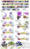
C10 HCDR3 interactions at the E dimer interface in the various structures, related to Figure 6 (A) The reference ZIKV sE/C10 Fab complex (Figure S2B, top panel; Table S2, first data column). For clarity, only one C10V is displayed as gray ribbons, while ZIKV sE is in yellow. As explained in the text, for the comparisons in the other panels all the sE / C10 half-dimer snapshots were aligned on the core epitope at the tip of domain II, as defined in Figure 3C. (B) View down the purple arrow in (A) comparing the reference structure to the available cryo-EM snapshots of the ZIKV virion, C10 bound (PDB: 5H37, 4Å resolution) and unbound (PDB:6C08, 3.1 Å resolution). For clarity, both sE and C10V of the reference structure are in yellow (here and in the middle panel of C-G below), and the various cryo-EM structures of the complex are displayed in a single color each, as indicated. The C10 paratope is presented with the HCDR3 (labeled as H3) projecting the prominent side chain of WH100D as sticks, and also labeling the LCDR1 and LCDR3 loops as L1 and L3. The main elements composing the epitope are also labeled: fusion loop (FL), ij hairpin, b strand, kl hairpin across the E dimer interface and the n1 3/10 helical turn of the bc loop, which participates in I2/L2 interdimer contacts on the virion (see Figure 6). The side chain of Ser285 at the end of β-strand l (corresponding to Phe 279 in DENV1, 2 and 4, and Phe277 in DENV3, see alignment in Figure S2A) is highlighted as sticks, as this residue is referred to in the other panels. This panel shows that the sE protein in the X-ray structure adopts a conformation that matches that of E on virions, as the observed differences can be attributed to the lower resolution of the cryo-EM structures. This observation validates our choice of this particular structure as reference for all our comparisons. (C-G) Comparative analysis of the various DENVs structural snapshots reported to the reference structure, to unbound sE structures and to the cryo-EM structure of C10 bound to the virion in the case of DENV2. The left panels correspond to the boxed region in panel A. For clarity, C10V is not shown, only the corresponding docking axes (extracted from the middle panel of Figure 5B). Sites 0, 1 and 2 are defined in the text and also in Figure S2, Figure S4C and S4). The middle panels show the same view as in panel B (down the arrow in (A), comparing in each case to the reference structure (yellow). The third panels compare the analyzed X-ray structures to various other structures available for E of the same virus, including the cryo-EM DENV2 / C10 structure presented here, and omitting the reference structure for clarity. Disordered regions are indicated in the middle and right panels by dotted lines of the same color as the ribbon diagram, with a thick red arrow highlighting them (C) DENV1 sE / C10 (Figure S2B, second panel; Table S2, second data column). The middle panel shows that the WH100D side chain adopts a different rotamer than in the complex with ZIKV sE, and that the ij hairpins essentially overlap. The kl hairpin is partially disordered (dotted lines, marked by the red arrow). The DENV1 Phe279 and ZIKV Ser285 side chains are shown as sticks as a guide, as they mark the base of the kl hairpin at the end of the l strand (see the sequence alignment in Figure S2A). The right panel compares the structures of C10-bound and unbound DENV1 sE (determined here as it was not available in the PDB; it is displayed in Figure S2F; see also Table S2, seventh data column). The unbound structure is not symmetrical as the C10 bound sE, and the kl hairpin is disordered (red arrow), with density for Phe279 only on one half sE dimer (gray sticks). The ij hairpin is significantly shifted up with respect to the C10 bound form. This comparison indicates that sE in solution samples a broad conformational landscape, and that crystal packing of the unbound form selects for on asymmetric conformation. C10 binding appears, on the contrary, to select a symmetric conformation that matches better the conformation on virions (as the ij hairpin in the C10 bound DENV1 sE is closer to the reference structure, compare middle and right panels). (D) DENV2 sE / C10, complex 1 (from PDB:4UTC). The crystals used to determine this structure had two sE dimers bound to C10 in the asymmetric unit, arbitrarily termed here dimers 1 and 2; sE dimer1 makes the raft-like rows displayed in Figure 6E. The two sE half dimers are differentiated in two shades of green. Note that, compared to the reference structure, the HCDR3 projects deeper into the sE dimer interface (3.1Å, as labeled in the middle panel). This is not the case on virions, where the HCDR3 enters the sE dimer interface as in the reference structure (compare the H3 loop in the middle (yellow) and right panels (blue/pink, with 3f site (in blue) being closest to the reference structure). Note also that on virions, Phe279 adopts a conformation closer to Ser285 in ZIKV (comparing with the middle panel) and points toward the E dimer interface. The curved black arrow in the right panel shows the transition of Phe279 from its location in the X-ray structures of sE (C10 bound and unbound) to that of E on virions. A similar change was observed in the first crystal structures reported for DENV2 sE (Modis et al., 2003), which showed a hydrophobic-ligand-binding pocket between the kl and fg hairpins (which are labeled in Figure 1A, bottom protomer) and in which the Phe279 side chain was found in different conformations depending on the presence or absence of the ligand. (E) DENV2 sE / C10, complex 2 (PDB:4UTC, second complex in the asymmetric unit), with the sE half dimers shown in light green and cyan (sites 1’ and 2′ respectively). The HCDR3 projects even deeper into sE dimer interface in site 2′, 5Å with respect to the reference structure (see middle panel), and the ij hairpin becomes disordered (red arrows). In site 1’, these elements remain similar to their counterpart in dimer 1 displayed in panel D. The Phe279 conformations also remain similar to those in dimer 1. (F) DENV3 sE / C10 complex (Figure S2B, third panel; Table S2, third data column). Different to the above panels, the middle panel shows, in addition to the two half sE dimers bound to C10 shown in dark blue and cyan, the structure of DENV3 sE bound to C8 (in purple/pink) (structure displayed in Figure S2E, see also Table S2, sixth data column). The kl hairpin is disordered in both DENV3 sE / C10 half dimers, but Phe277 (corresponding to Phe 279 in DENV2) is ordered in site 2 and oriented toward the sE dimer interface, although in a different conformation to Phe 279 on virions (compare the right panel with the panel immediately above). Compared to the DENV2 complexes, the C10 HCDR3 inserts at an angle, directed more toward the opposite sE subunit in the dimer (shifted by 3.6Å, labeled in the middle panel), and the side chain of WH100D displays different rotamers in the two sites. The rotamer in site 2 interacts with a disordered ij hairpin (tilted red arrows). The DENV3 sE complex with C8 resulted in a symmetric, crystallographic dimer, in which both the ij and the kl hairpins were ordered. A crystal of unbound DENV3 sE had been reported to 3.7 Å resolution (Modis et al., 2005). Here we obtained crystals of unbound DENV3 sE which diffracted to 2.8Å resolution. The corresponding structure (Figure S2F; Table S2, eighth data column) showed an asymmetric sE dimer in which the kl hairpin was disordered (right panel). (G) the DENV4 sE / C10 complex (Figure S2B, fourth panel; Table S2, fourth data column. The half-dimer snapshots are shown in violet (site 1) and magenta (site 2). The HCDR3 loop inserts deep in site 2, pushing the ij hairpin toward the bottom (shown also in Figure S2D, inset) and a disordered kl hairpin. In the purple half-dimer, the ij loop is disordered despite a moderate insertion, similar to the ZIKV sE/ C10 complex (compared in the middle panel). There are no available structure of unbound DENV4 sE, so in the third panel we compare the DENV4 sE / C10 snapshots with the structure of DENV sE in complex with Mab 5H2 (Cockburn et al., 2012), whose epitope is away from the EDE. That structure was also not symmetrical, and so two half-sites are compared. A pattern similar to those described above is observed with respect to the kl hairpin and the orientation of Phe279.
Figure 6
Figure 6
sE crystal packing mimics the lateral I2/L2 E dimer contacts on virions (A) View down an I2 axis of the 2.5-Å cryo-EM structure of the DENV2 virion (PDB: 7KV8) (Hardy et al., 2021). The segment with secondary structure elements h-h’-i-j-α2-k-l, is highlighted in a color ramp from the N to the C terminus (corresponding to aa 218–282 for DENV2 E; see Figure S2A, color key to the right). This segment is central to the E dimer and is involved in intradimer packing via the α2 helix and interdimer packing via the hh’ hairpin, which contacts the bc loop of the adjacent E dimer via residues in the n1 turn (labeled). It is also involved in contacts with the underlying M protein via the ij hairpin and the α2 helix as well as in determining E dimer curvature via the kl hairpin. A magenta outline indicates the location of the C10 epitope to the left. (B–E) The hh’/ bc loop interdimer packing is preserved in the X-ray structures but is affected when both epitopes in the DENV2 sE dimer are bound by C10. The first column shows an open book view of the I2/L2 dimer contacts on the virion or between sE dimers in the crystals, with the BSA quoted. The second column shows the lateral packing of E dimers on virions or sE dimers in the crystals, as indicated, with a frame marking the enlarged area shown in the right panels. The quasi-2-fold (Q2) axes relating I2 and L2 dimers on virions, or crystallographic axes relating adjacent dimers in the crystals, are displayed in green. The third and fourth columns show a closeup of these contacts in two orthogonal views, highlighting the interaction between the hh’ hairpin in one dimer with the bc loop (highlighted by labeling the η1 turn) of the adjacent dimer. The Q2 or strict 2-fold interdimer axis is marked by an empty or full oval, respectively. Hydrogen bonds across the dimer/dimer interface are shown as dotted lines. (B) L2 and I2 dimers on the Zika virion (PDB: 6CO8). (C) Adjacent dimers in the crystals of ZIKV sE/C10. Empty arrows indicate that the row of sE dimers extends indefinitely in the crystals. (D) Packing of I2 and L2 dimers in the C10-bound virion with roughly 50% occupancy, averaging E dimers with C10 bound at the 3f or 5f epitope. (E) sE dimer rows in theDENV2 sE/C10 crystals. In this structure, the dimers show propensity to pack in the same way as on the virion and on the crystals of the ZIKV/C10 complex (as in B–D), but the altered conformation of the sE dimer selected by C10 binding at both sites in solution results in a conformation in which the hh’ hairpin faces the bc loop at one side only, losing the 2-fold symmetry of the contact (last panel, shift marked with an arrow).
Figure S6
Figure S6
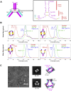
Bivalent C10 is unable to bind intradimer epitopes, related to Figure 7 (A) Diagram of a human IgG1 molecule (top) and sequence of the hinge linking Fab and Fc (inset, corresponding to the boxed area in the diagram). The heavy and light chains are represented in magenta and cyan, respectively. (B) SEC/MALS analysis of the isolated ZIKV sE, F(ab’)2 C10 alone and in complex with ZIKV sE (top-left panel); and of ZIKV sE, IgG C10 alone and in complex with ZIKV sE (top-right panel). The molecular weight determined by MALS is indicated, corresponding to the y axis on left. The cartoons illustrate the molecular complexes inferred from the molecular weights derived by MALS. The bottom panels show the SEC/MALS profile of ZIKV sE with IgG C8 (left panel) and with the FLE IgG P6B10 (right panel) alone and in complex. (C) Top, raw transmission electron micrograph of negative stained ZIKV sE / F(ab’)2 C10 complex. Middle panel, 2D class average of the complex with two major classes observed. Bottom, 3D cartoon representations of the two classes.
Figure S7
Figure S7
ZIKV sE in complex with bivalent C10, related to Figure 7 (A) Fab C10 elbow angle from the X-ray structures of the ZIKV sE in complex with Fab C10 (yellow), with F(ab’)2 C10 (magenta), and as modeled on the virion (blue). The Fabs were superposed on the variable domains (green axis). The angles were calculated using the online AS2TS server (Zemla et al., 2005). In the F(ab’)2 C10, the constant domain rotated by 1.2° toward its coupled arm, and a further 6.7° bending was required to connect the two Fab arms via an extended hinge when modeled on the 3f epitopes. The elbow angle of 221.5° is within the accessible range, which spans from 132° to 225°, as shown in panel D (B) Electron density of the refined ZIKV sE / F(ab’)2 X-ray for the linker between the two Fab arms displayed at a low contour level (0.5 σ). The polypeptide chain was modeled only tentatively for representation purposes, as the density was very weak. This region is thus not present in the coordinates file deposited in the PDB. (C) Range of Fab elbow angles in selected structures from PDB database, ramp colored from red (smallest, 132°) to blue (largest, 225°) through yellow and green, and with the disulfide bond between CL211 and CH216 drawn as spheres. The PDB codes of the Fab structures with most extreme elbow angles are indicated. The CH216 Cα atom has an accessible range of about 50Å along the direction of the curved arrow (i.e, in the plane of the Figure). In our two crystal structures, the C10 Fab has a relatively large elbow angle (∼213 o). (D) The IgG1 hinge segment extended to display the maximal distance between the CH216 and CH222 Cα atoms, which make disulfide bonds with the light chain CL211 in the Fab and with CH222 in the partner heavy chain of the antibody, respectively. This panel shows that the hinge between the two Fab arms of an IgG1 molecule, measured between the two CH216 Cα atoms can be stretched until ∼50 Å at most (i.e., the maximum distance is slightly longer than the distance of the fully stretched segment between the CH216 and CH222 Cα atoms in each heavy chain, allowing for the interchain disulfide bond). Although 50Å would then be the theoretical limit, this distance requires a fully stretched hinge segment, and can potentially be reached in the most favorable orientations of the two Fab arms with respect to each other. (E)-(F) These panels analyze potential bivalent binding within a raft (E) and across rafts (F). The combined flexibility about the Fab elbow angle and stretching of the heavy chain hinge allows bivalent IgG binding to only certain epitopes on virions. These panels show the antibody docked at the various epitopes with the whole range of elbow angles as shown in panel C. The shortest distances between the CH216 Cα atoms (using the adequate elbow angle, colored as in panel C) of adjacent Fabs are displayed. For instance, in panel E, dotted lines between Fab arms bound at the I2 dimer (the central white dimer) show that the closest distance is ∼100Å, demonstrating that these two epitopes cannot be bound by the Fab arms of the same IgG molecule, in line with the results in Figure S6. Although panel E shows Fab pairs different from those bound to the two 3f epitopes spanning distances under 50Å, they involve in each case one 2f epitope, which is bound poorly by C10, as shown by the cryo-EM reconstruction. Panel F suggests that inter-raft divalent binding to two adjacent 5f epitopes could be feasible, as the closest distance is 47Å (bottom right). Yet contrary to the two Fab arms bound at the 3f epitopes (shown in panel E at the center), in the inter-raft connection the Fabs cannot bend toward each other within the same vertical plane, but their mobility is about different planes and the linker requires some twisting to reach the second Fab, reducing the range it can extend. (G) Attempts to image of ZIKV virions with C10 F(ab’)2 by cryo-EM resulted in particle aggregation, as shown in the field view in the left panel. IgG1 C10 can bind bivalently to 3f epitopes, and leaves the 5f sites available for crosslinking (as outlined in the right panel) and precipitation of the sample. If the C10 F(ab’)2 could readily bind bivalently at the 5f epitopes, the prediction would be that the virions would be less prone to aggregation.
Figure 7
Figure 7
C10 binds bivalently at both 3f epitopes per raft (A) Left: crystals of the ZIKV sE/C10 F(ab’)2 complex are formed of rows in which sE dimers pack laterally as in a raft (highlighted by a green contour). E dimers in the row are shown alternating white with light/dark gray dimers, as in Figures 1B and 4B. The cyan/magenta F(ab’)2 is related by the 2-fold molecular axis of a white dimer, and its Fab arms are bound to each of the two light/dark gray E dimers at either side. Similarly, the yellow F(ab’)2 shares the 2-fold molecular axis of a light/dark gray dimer and is bound to the two white dimers at either side, and so on. The hinge between the two Fab arms was modeled into weak density (Figure S7B). The panel on the right shows a side view of the row with only one C10 F(ab’)2 displayed for clarity. The distance between two heavy-chain CH231 Cα atoms and the elbow angle are indicated. The gel at the bottom left displays SDS-PAGE of the sE/F(ab’)2 complex isolated from a SEC column (lane 1) and from re-dissolved crystals (lane 2), demonstrating the presence of intact F(ab’)2 in the crystal. Lane M displays molecular weight markers (labeled at the left of the gel). (B) A F(ab’)2 C10 modeled on the Zika virion (PDB: 5H37) bound to the raft outlined in green. The right panel shows that the raft is curved, unlike the flat rows observed in the crystal shown directly above (in A). A change in the elbow angle brings the C-terminal ends of the C10 Fab heavy chain within reach of the CH1-CH2 hinge.

Comment in

Similar articles

Cited by

References

    1. Añez G., Heisey D.A., Volkova E., Rios M. Complete Genome Sequences of Dengue Virus Type 1 to 4 Strains Used for the Development of CBER/FDA RNA Reference Reagents and WHO International Standard Candidates for Nucleic Acid Testing. Genome Announc. 2016;4 e01583-15. - PMC - PubMed
    1. Barba-Spaeth G., Dejnirattisai W., Rouvinski A., Vaney M.C., Medits I., Sharma A., Simon-Lorière E., Sakuntabhai A., Cao-Lormeau V.M., Haouz A., et al. Structural basis of potent Zika-dengue virus antibody cross-neutralization. Nature. 2016;536:48–53. - PubMed
    1. Baronti C., Piorkowski G., Charrel R.N., Boubis L., Leparc-Goffart I., de Lamballerie X. Complete coding sequence of zika virus from a French polynesia outbreak in 2013. Genome Announc. 2014;2 e00500-14. - PMC - PubMed
    1. Bhatt S., Gething P.W., Brady O.J., Messina J.P., Farlow A.W., Moyes C.L., Drake J.M., Brownstein J.S., Hoen A.G., Sankoh O., et al. The global distribution and burden of dengue. Nature. 2013;496:504–507. - PMC - PubMed
    1. Blanc E., Roversi P., Vonrhein C., Flensburg C., Lea S.M., Bricogne G. Refinement of severely incomplete structures with maximum likelihood in BUSTER-TNT. Acta Crystallogr. D Biol. Crystallogr. 2004;60:2210–2221. - PubMed

Publication types

MeSH terms