. 2021 Dec:81:105847.
doi: 10.1016/j.ultsonch.2021.105847. Epub 2021 Nov 26.

Turbulence-induced formation of emulsion gels

Affiliations

Turbulence-induced formation of emulsion gels

Wu Li et al. Ultrason Sonochem. 2021 Dec.

Abstract

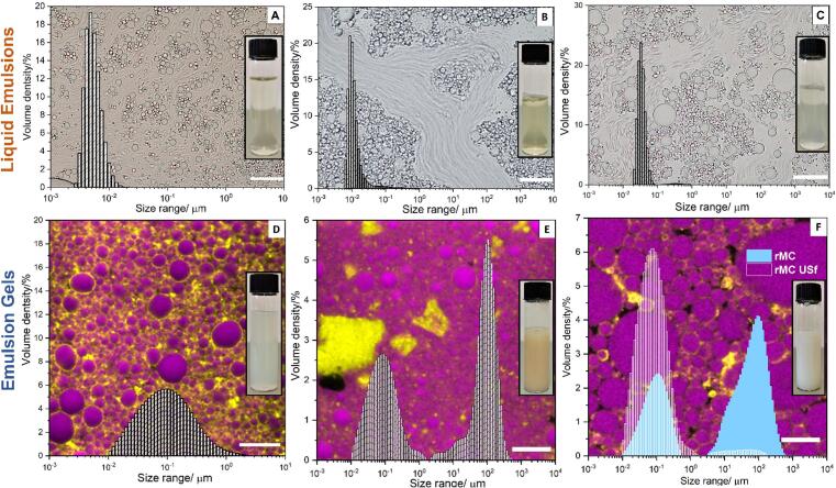
Emulsion gels have a wide range of applications. We report on a facile and versatile method to produce stable emulsion gels with tunable rheological properties. Gel formation is triggered by subjecting a mixture containing aqueous colloidal particle (CP) suspensions and water-immiscible liquids to intense turbulence, generated by low frequency (20 kHz) ultrasound or high-pressure homogenization. Through systematic investigations, requisite gel formation criteria are established with respect to both formulation and processing, including ratio/type of liquid pairs, CP properties, and turbulence conditions. Based on the emulsion microstructure and rheological properties, inter-droplet bridging and CP void-filling are proposed as universal stabilization mechanisms. These mechanisms are further linked to droplet-size scaling and sphere close-packing theory, distinctive from existing gel-conferring models. The study thereby provides the foundation for advancing the production of emulsion gels that can be tailored to a wide range of current and emerging applications in the formulation and processing of food, cosmetics or pharmaceutical gels, and in material science.

Keywords: Colloidal Particles; Emulsion Gels; Turbulent Flow; Ultrasound.


Conflict of interest statement

The authors declare that they have no known competing financial interests or personal relationships that could have appeared to influence the work reported in this paper.

Figures

None
Graphical abstract
Fig. 1
Fig. 1
Demonstration of the need for high-intensity turbulence to trigger emulsion gel formation, with examples using three types of colloidal stabilizers. Comparison of the microstructure and bulk texture of emulsions formed at prolonged low-intensity emulsification using an Ultra-Turrax (UT) rotor–stator mixer (A, B and C, respectively), and a short pulse with high-intensity emulsification using high-intensity low-frequency ultrasound (HILF-US, also achievable using high-pressure homogenization, HPH) (D, E and F, respectively). Sunflower oil (SFO) was the oil phase at 0.5 v/v. Optical microscopic images of microstructures of emulsions stabilized by bovine micellar casein (BMC) (100 mg mL−1), TiO2 particles (P25, 100 mg mL−1), and graphene oxide (GO) (10 mg mL−1) are presented in the left (A and D), middle (B and E) and right (C and F) columns, respectively. Scale bars: 20 µm. Macroscopic representations (images) of the gels are presented as inserts.
Fig. 2
Fig. 2
Microstructure of liquid emulsions (top row) and emulsion gels (bottom row) produced by HILF-US emulsification. Superimposed are the volume size distributions of the corresponding colloidal particle (CP) stabilizers and images of the clear (top row) and turbid (bottom row) suspensions. Optical microscopic images of liquid emulsions under long exposure (200 ms) prepared with WPI (A, 50 mg mL−1), SPI supernatant (B, 25 mg mL−1), and SC (C, 50 mg mL−1), where fast-moving droplets became blurred. Confocal microscopic images of WPP (D, 50 mg mL−1), SPI (E, 100 mg mL−1) and rMC (F, 25 mg mL−1) emulsion gels. (F) Size distributions of rMC suspension before (solid-blue symbol) and after (rMC USf, open-white). Scale bars: 20 μm (A, B, C, and F) and 10 μm (D and E).
Fig. 3
Fig. 3
Dependence of TIEG formation on the oil fraction and type. Optical microscopy images of BMC-SFO emulsions (10 mg mL−1) subjected to HILF-US emulsification (70 J mL−1, A, C and E) and UT (300 J mL−1, B, D, and F) at OF = 0.2, 0.5, and 0.7. Visualization of the macroscopic texture difference of emulsions formed by HILF-US and UT at OF = 0.5 (G). Scale bars: 20 µm (A – D), 200 µm (E and F) and 1 mm (G). Strain oscillatory sweep profiles (H) of BMC-SFO emulsions (HILF-US) within 0.01 – 1000% oscillating strain (γ) of emulsions at OF = 0.3, 0.4, 0.5, 0.6 and 0.7 (G’ and G’’ represented with closed and open symbols, respectively). Zero-shear elastic moduli (G0′) of GO (10 mg mL−1, grey columns) and chitosan (pH = 6.5, 20 mg mL−1, white columns) emulsions (I, OF = 0.5 v/v) prepared with cyclohexane, dodecane and hexadecane. The picture insert shows the texture of corresponding GO-alkane emulsions (left to right, cyclohexane, dodecane and hexadecane, 20 J mL−1, 3 mm HILF-US microtip).
Fig. 4
Fig. 4
SEM images of microstructures of TIEG-derived from BMC-cyclohexane (100 mg mL−1) (A and D), GO-dodecane (15 mg mL−1) (B and E) and P25-dodecane (100 mg mL−1, 60 mM NaCl) aerogels (C and F). The estimated wall thickness of IDB was approximately 101, 100 and 102 nm, respectively. The effective IDB unit was speculated to be single-layer interfacially-deformed BMC films (indicated by arrows, D), thin layers of GO sheets (E), and deformed clusters of P25 (F), corresponding to the schematic illustrations (G-I). Scale bars: 5 µm (A and B), 50 µm (C), 500 nm (D and E), and 20 µm (F).
Fig. 5
Fig. 5
Connection between 2D Apollonian gasket model (A-C) and microstructural evidence (D and E) of CVF stabilization in TIEG. Schematic diagram of the fractal-like close packing based on three consecutive filling iterations starting from three mother droplets with IDB configuration, including two IDB steps (A and B) and the appearance of CVF in the third void filling iteration (C). The diameters of IDB droplets and CPs undergo CVF (before deformation, indicated with light blue dashed circle) were calculated and labeled correspondingly (in microns) based on a given diameter (10 µm) of the three mother droplets, resulting in the overall reduction of length scale from 101 – 10-1 µm. In SEM images of a PPI (PPI-cyclohexane, 100 mg mL−1, OF = 0.5 v/v) aerogel, the extremely thin IDB sites exhibit web-like networks, which could be due to the damage caused by the freeze-drying process (D). A higher magnification (E, the zoomed-in area indicated by the white-dashed box in D) revealed a cross-section of the IDB-CVF transition, where the gradual increase (1–5) in cell wall thickness is recorded in the table. Scale bars: 1 µm (D), and 500 nm (E). A comparable section of the microstructure shown in E is indicated in the model diagram (C). The dispersed phase droplet is labeled with the asterisk and the transition of IDB site to CVF center is indicated using white-dashed lines.
Fig. 6
Fig. 6
Effects of CP concentration and dimensional alteration on IDB-CVF stabilization in BMC (A and C, 10 and 100 mg mL−1, BMC-cyclohexane, OF = 0.5 v/v) and GO (B, GO-dodecane, 15 mg mL−1, and D, GO/rGO-cyclohexane, 10 mg mL−1, partially reduced by ascorbic acid, OF = 0.5 v/v) TIEGs. The presence of CVF effect can be observed from the inner droplet curvature at high BMC concentration (C, indicated by arrows), which is absent in the low concentration counterpart (A). 2D single-layer GO sheets (B, 15 mg mL−1) were not capable of providing effective CVF. (D) Similar vein-like morphology is visible (indicated by arrows) potentially due to the 3D profile of reduced GO self-assemblies (10 mg mL−1) (I). Scale bars: 10 µm.
Fig. 7
Fig. 7
Schematic illustration of TIEG formation mechanism. Emulsion formulation factors including oil fraction and type (e.g. alkanes and triglycerides) and physical properties of CP (e.g. particle size) were shown to be central to TIEG formation. High-intensity turbulent conditions are needed to physically trigger the TIEGs from emulsions with requisite compositions. The macroscopic liquid-gel transition can be related to universal droplet stabilization mechanisms: IDB and CVF provide stabilization at droplet–droplet interfaces and within inter-droplet aqueous voids, respectively. High-intensity micro-turbulence is required to create sufficiently fine droplets and aqueous void spaces able to directly accommodate the remaining CPs as the second group of 3D subjects, therefore, initiating CVF stabilization. Given the same emulsion formulation, low-intensity macro-turbulence poses limited droplet splitting capability, which leads to the absence of CVF and high droplet mobility within the continuous (aqueous) phase, hence macroscopic free-flowing liquids.

References

    1. Dickinson E. Emulsion gels: the structuring of soft solids with protein-stabilized oil droplets. Food Hydrocolloids. 2012;28(1):224–241.
    1. Lupi F.R., Gabriele D., Seta L., Baldino N., de Cindio B., Marino R. Rheological investigation of pectin-based emulsion gels for pharmaceutical and cosmetic uses. Rheol. Acta. 2015;54(1):41–52.
    1. Hu Z., Patten T., Pelton R., Cranston E.D. Synergistic stabilization of emulsions and emulsion gels with water-soluble polymers and cellulose nanocrystals. ACS Sustainable Chem. Eng. 2015;3(5):1023–1031.
    1. Gallegos C., Franco J.M. Rheology of food, cosmetics and pharmaceuticals. Curr. Opin. Colloid Interface Sci. 1999;4(4):288–293.
    1. Barg S., Perez F.M., Ni N., do Vale Pereira P., Maher R.C., Garcia-Tuñon E., Eslava S., Agnoli S., Mattevi C., Saiz E. Mesoscale assembly of chemically modified graphene into complex cellular networks. Nat. Commun. 2014;5(1) doi: 10.1038/ncomms5328. - DOI - PMC - PubMed

LinkOut - more resources