

Robotic Milling of Electrode Lead Channels During Cochlear Implantation in an ex-vivo Model
- PMID: 34859039
- PMCID: PMC8631814
- DOI: 10.3389/fsurg.2021.742147
Robotic Milling of Electrode Lead Channels During Cochlear Implantation in an ex-vivo Model
Abstract
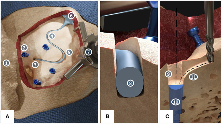
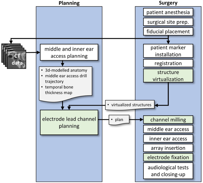
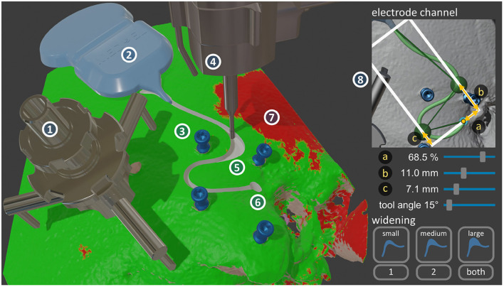
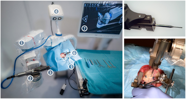
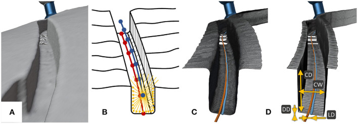
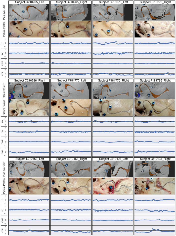
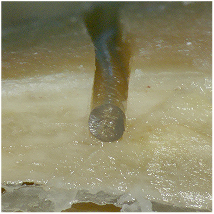
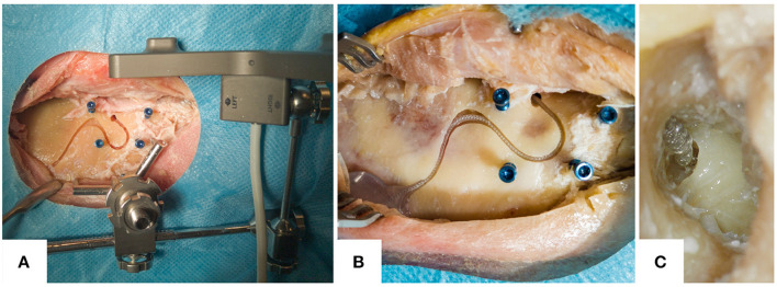
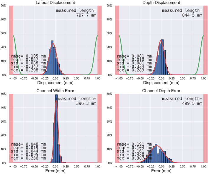
Objective: Robotic cochlear implantation is an emerging surgical technique for patients with sensorineural hearing loss. Access to the middle and inner ear is provided through a small-diameter hole created by a robotic drilling process without a mastoidectomy. Using the same image-guided robotic system, we propose an electrode lead management technique using robotic milling that replaces the standard process of stowing excess electrode lead in the mastoidectomy cavity. Before accessing the middle ear, an electrode channel is milled robotically based on intraoperative planning. The goal is to further standardize cochlear implantation, minimize the risk of iatrogenic intracochlear damage, and to create optimal conditions for a long implant life through protection from external trauma and immobilization in a slight press fit to prevent mechanical fatigue and electrode migrations. Methods: The proposed workflow was executed on 12 ex-vivo temporal bones and evaluated for safety and efficacy. For safety, the difference between planned and resulting channels were measured postoperatively in micro-computed tomography, and the length outside the planned safety margin of 1.0 mm was determined. For efficacy, the channel width and depth were measured to assess the press fit immobilization and the protection from external trauma, respectively. Results: All 12 cases were completed with successful electrode fixations after cochlear insertions. The milled channels stayed within the planned safety margins and the probability of their violation was lower than one in 10,000 patients. Maximal deviations in lateral and depth directions of 0.35 and 0.29 mm were measured, respectively. The channels could be milled with a width that immobilized the electrode leads. The average channel depth was 2.20 mm, while the planned channel depth was 2.30 mm. The shallowest channel depth was 1.82 mm, still deep enough to contain the full 1.30 mm diameter of the electrode used for the experiments. Conclusion: This study proposes a robotic electrode lead management and fixation technique and verified its safety and efficacy in an ex-vivo study. The method of image-guided robotic bone removal presented here with average errors of 0.2 mm and maximal errors below 0.5 mm could be used for a variety of other otologic surgical procedures.
Keywords: electrode fixation; electrode lead channel; ex-vivo human cephalic study; image-guidance; patient-specific planning; robotic cochlear implantation; robotic milling; robotic surgery.
Copyright © 2021 Hermann, Mueller, Schneider, O'Toole Bom Braga and Weber.
Conflict of interest statement
SW is cofounder, shareholder, and chief executive officer of CASCINATION AG (Bern, Switzerland), which commercializes the robotic cochlear implantation technology. The remaining authors declare that the research was conducted in the absence of any commercial or financial relationships that could be construed as a potential conflict of interest.
Figures
Similar articles
-
Image-Based Planning of Minimally Traumatic Inner Ear Access for Robotic Cochlear Implantation.Front Surg. 2021 Nov 25;8:761217. doi: 10.3389/fsurg.2021.761217. eCollection 2021. Front Surg. 2021. PMID: 34901143 Free PMC article.
-
In vitro accuracy evaluation of image-guided robot system for direct cochlear access.Otol Neurotol. 2013 Sep;34(7):1284-90. doi: 10.1097/MAO.0b013e31829561b6. Otol Neurotol. 2013. PMID: 23921934
-
First Study in Men Evaluating a Surgical Robotic Tool Providing Autonomous Inner Ear Access for Cochlear Implantation.Front Neurol. 2022 Mar 21;13:804507. doi: 10.3389/fneur.2022.804507. eCollection 2022. Front Neurol. 2022. PMID: 35386404 Free PMC article.
-
Robotic Cochlear Implantation for Direct Cochlear Access.J Vis Exp. 2022 Jun 16;(184). doi: 10.3791/64047. J Vis Exp. 2022. PMID: 35786698 Review.
-
Robotics and cochlear implant surgery: goals and developments.Curr Opin Otolaryngol Head Neck Surg. 2022 Oct 1;30(5):314-319. doi: 10.1097/MOO.0000000000000837. Curr Opin Otolaryngol Head Neck Surg. 2022. PMID: 36036531 Review.
References
-
- Weinreich HM, Francis HW, Niparko JK, Chien WW. Techniques in cochlear implantation. Oper Tech Otolaryngol-Head Neck Surg. (2014) 25:312–20. 10.1016/j.otot.2014.09.002 - DOI
-
- Friedmann DR, Jethanamest D, Roland JT, Jr. Surgery for cochlear implantation: standard approach. in Cochlear Implants: From Principles to Practice. JP Medical Ltd. p.47–54.