

Concurrent Validity of Power From Three On-Water Rowing Instrumentation Systems and a Concept2 Ergometer
- PMID: 34867462
- PMCID: PMC8633434
- DOI: 10.3389/fphys.2021.758015
Concurrent Validity of Power From Three On-Water Rowing Instrumentation Systems and a Concept2 Ergometer
Abstract
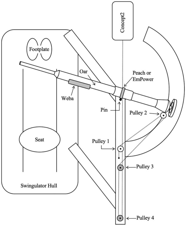
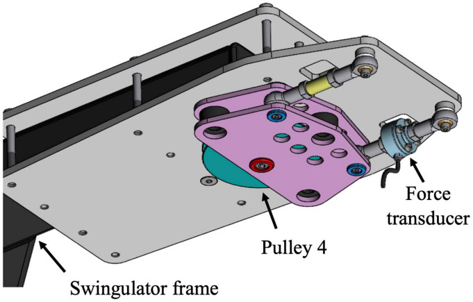
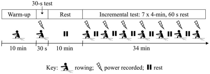
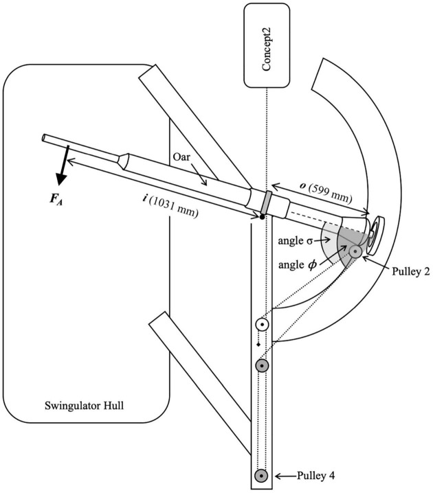
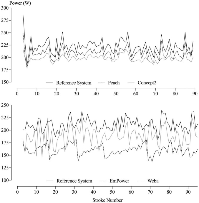
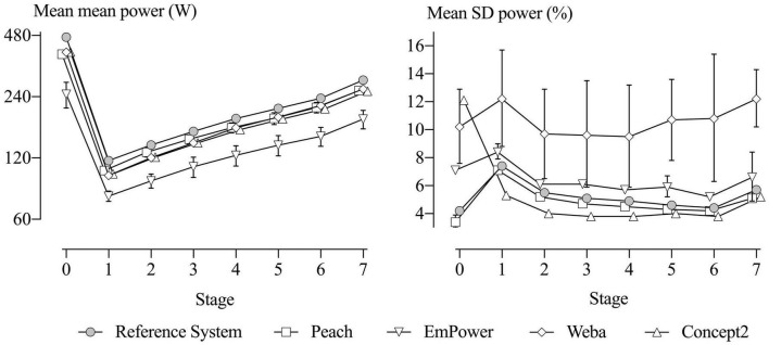
Purpose: Instrumentation systems are increasingly used in rowing to measure training intensity and performance but have not been validated for measures of power. In this study, the concurrent validity of Peach PowerLine (six units), Nielsen-Kellerman EmPower (five units), Weba OarPowerMeter (three units), Concept2 model D ergometer (one unit), and a custom-built reference instrumentation system (Reference System; one unit) were investigated. Methods: Eight female and seven male rowers [age, 21 ± 2.5 years; rowing experience, 7.1 ± 2.6 years, mean ± standard deviation (SD)] performed a 30-s maximal test and a 7 × 4-min incremental test once per week for 5 weeks. Power per stroke was extracted concurrently from the Reference System (via chain force and velocity), the Concept2 itself, Weba (oar shaft-based), and either Peach or EmPower (oarlock-based). Differences from the Reference System in the mean (representing potential error) and the stroke-to-stroke variability (represented by its SD) of power per stroke for each stage and device, and between-unit differences, were estimated using general linear mixed modeling and interpreted using rejection of non-substantial and substantial hypotheses. Results: Potential error in mean power was decisively substantial for all devices (Concept2, -11 to -15%; Peach, -7.9 to -17%; EmPower, -32 to -48%; and Weba, -7.9 to -16%). Between-unit differences (as SD) in mean power lacked statistical precision but were substantial and consistent across stages (Peach, ∼5%; EmPower, ∼7%; and Weba, ∼2%). Most differences from the Reference System in stroke-to-stroke variability of power were possibly or likely trivial or small for Peach (-3.0 to -16%), and likely or decisively substantial for EmPower (9.7-57%), and mostly decisively substantial for Weba (61-139%) and the Concept2 (-28 to 177%). Conclusion: Potential negative error in mean power was evident for all devices and units, particularly EmPower. Stroke-to-stroke variation in power showed a lack of measurement sensitivity (apparent smoothing) that was minor for Peach but larger for the Concept2, whereas EmPower and Weba added random error. Peach is therefore recommended for measurement of mean and stroke power.
Keywords: Concept2; Nielsen-Kellerman EmPower; Peach PowerLine; Weba OarPowerMeter; between-unit differences; random error; systematic error; technical error of measurement.
Copyright © 2021 Holt, Hopkins, Aughey, Siegel, Rouillard and Ball.
Conflict of interest statement
The authors declare that the research was conducted in the absence of any commercial or financial relationships that could be construed as a potential conflict of interest.
Figures
Similar articles
-
Prediction of 2000-m on-water rowing performance with measures derived from instrumented boats.Scand J Med Sci Sports. 2022 Apr;32(4):710-719. doi: 10.1111/sms.14125. Epub 2022 Jan 20. Scand J Med Sci Sports. 2022. PMID: 34981575
-
Technical Determinants of On-Water Rowing Performance.Front Sports Act Living. 2020 Dec 3;2:589013. doi: 10.3389/fspor.2020.589013. eCollection 2020. Front Sports Act Living. 2020. PMID: 33345160 Free PMC article.
-
Power responses of a rowing ergometer: mechanical sensors vs. Concept2 measurement system.Int J Sports Med. 2006 Oct;27(10):830-3. doi: 10.1055/s-2006-923774. Epub 2006 Apr 11. Int J Sports Med. 2006. PMID: 16612738
-
Measures of rowing performance.Sports Med. 2012 Apr 1;42(4):343-58. doi: 10.2165/11597230-000000000-00000. Sports Med. 2012. PMID: 22401296 Review.
-
Strength testing and training of rowers: a review.Sports Med. 2011 May 1;41(5):413-32. doi: 10.2165/11588540-000000000-00000. Sports Med. 2011. PMID: 21510717 Review.
Cited by
-
Quantifying on-water performance in rowing: A perspective on current challenges and future directions.Front Sports Act Living. 2023 Mar 16;5:1101654. doi: 10.3389/fspor.2023.1101654. eCollection 2023. Front Sports Act Living. 2023. PMID: 37008623 Free PMC article.
-
On-water Rowing Biomechanical Assessment: A Systematic Scoping Review.Sports Med Open. 2024 Sep 27;10(1):101. doi: 10.1186/s40798-024-00760-2. Sports Med Open. 2024. PMID: 39331267 Free PMC article.
-
Reliable Peak Power Assessment During Concentric and Flexion-Extension-Cycle Based Rowing Strokes using a Non-Modified Rowing Ergometer.J Sports Sci Med. 2022 Feb 15;21(1):131-136. doi: 10.52082/jssm.2022.131. eCollection 2022 Mar. J Sports Sci Med. 2022. PMID: 35250343 Free PMC article.
-
Using Wearable Sensors to Estimate Mechanical Power Output in Cyclical Sports Other than Cycling-A Review.Sensors (Basel). 2022 Dec 21;23(1):50. doi: 10.3390/s23010050. Sensors (Basel). 2022. PMID: 36616649 Free PMC article. Review.
References
-
- Aisbett J., Lakens D., Sainani K. (2020). Magnitude based inference in relation to one-sided hypotheses testing procedures. SportRxix [preprint] 10.31236/osf.io/pn9s3 - DOI - PubMed
-
- Coker J. (2010). Using a Boat Instrumentation System to Measure and Improve Elite On-Water Sculling Performance. Ph.D. thesis. Auckland: Auckland University of Technology.
-
- Coker J., Hume P., Nolte V. (2009). Validity of the powerline boat instrumentation system. Int. Soc. Biomech. Sports 11 65–68.
-
- Dudhia A. (2017). The Physics of Rowing. Oxford: Oxford University.
LinkOut - more resources
Full Text Sources