. 2022 Jan;14(1):32-39.
doi: 10.1038/s41557-021-00830-y. Epub 2021 Dec 6.

Non-equilibrium conditions inside rock pores drive fission, maintenance and selection of coacervate protocells

Affiliations

Non-equilibrium conditions inside rock pores drive fission, maintenance and selection of coacervate protocells

Alan Ianeselli et al. Nat Chem. 2022 Jan.

Abstract

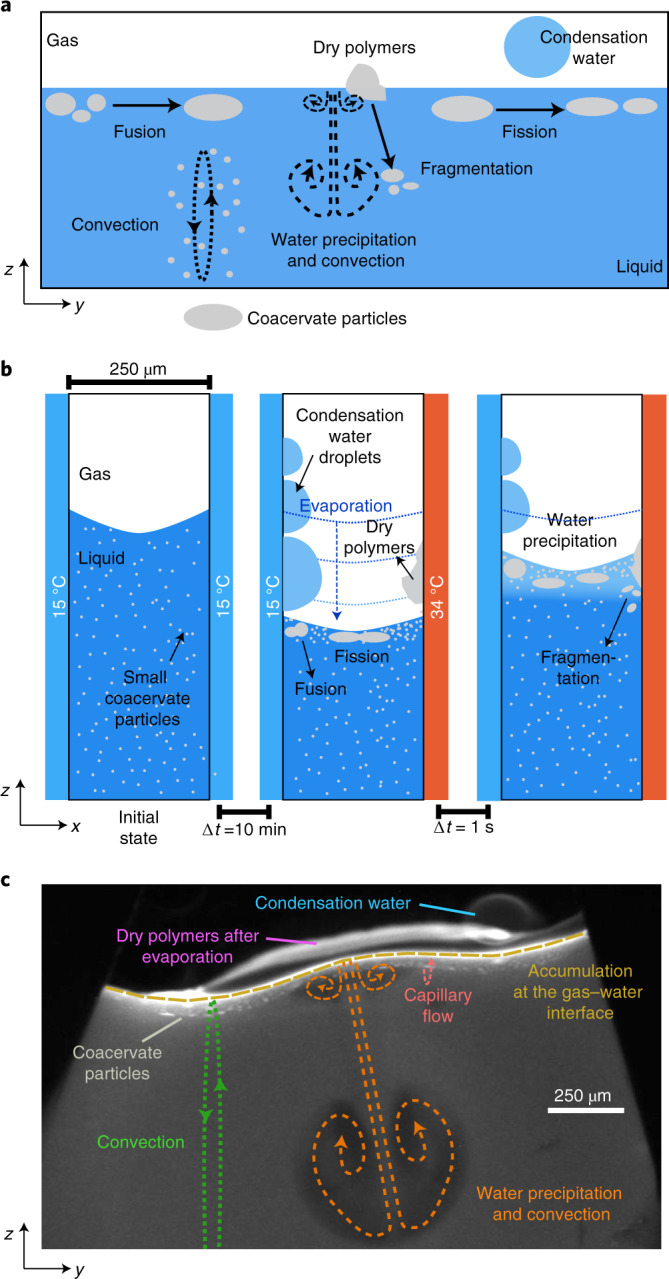
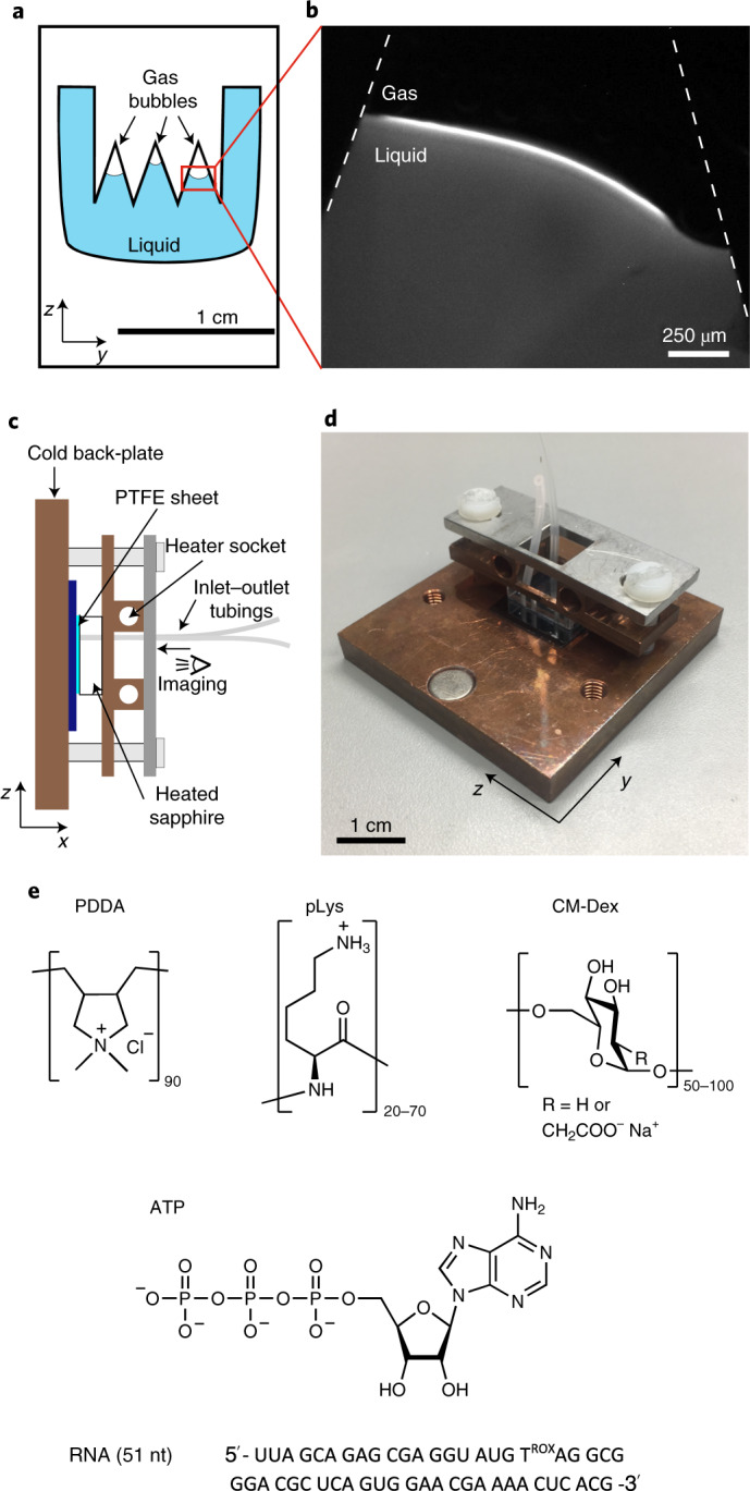
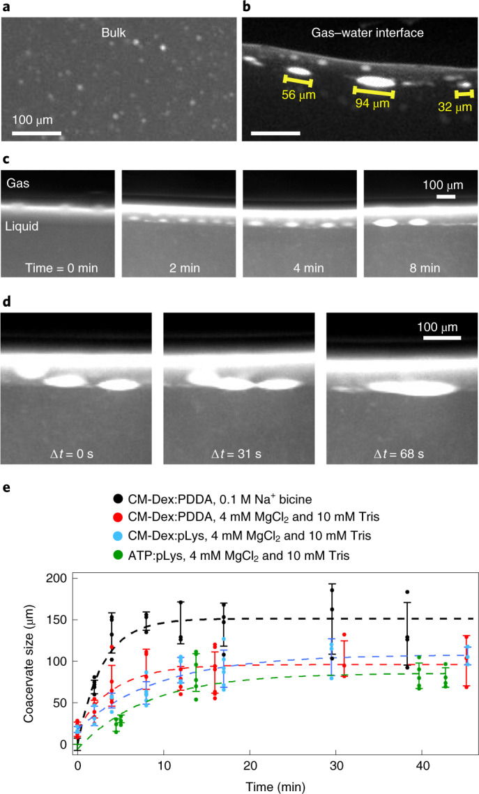
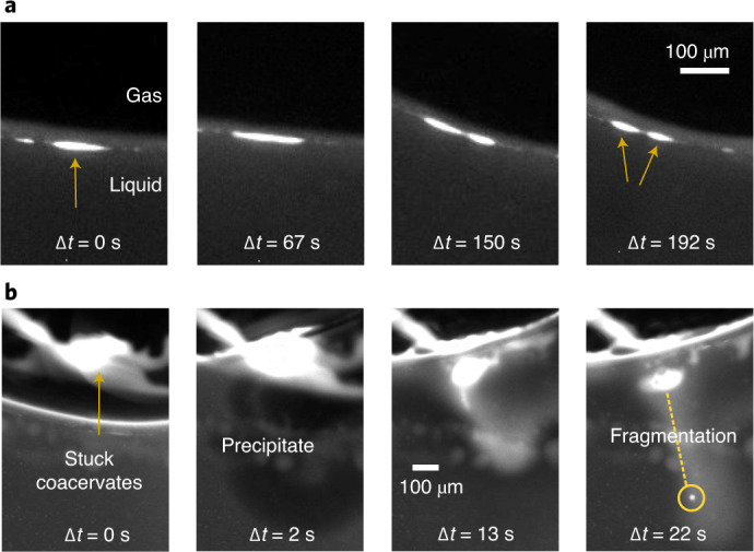
Key requirements for the first cells on Earth include the ability to compartmentalize and evolve. Compartmentalization spatially localizes biomolecules from a dilute pool and an evolving cell, which, as it grows and divides, permits mixing and propagation of information to daughter cells. Complex coacervate microdroplets are excellent candidates as primordial cells with the ability to partition and concentrate molecules into their core and support primitive and complex biochemical reactions. However, the evolution of coacervate protocells by fusion, growth and fission has not yet been demonstrated. In this work, a primordial environment initiated the evolution of coacervate-based protocells. Gas bubbles inside heated rock pores perturb the coacervate protocell distribution and drive the growth, fusion, division and selection of coacervate microdroplets. Our findings provide a compelling scenario for the evolution of membrane-free coacervate microdroplets on the early Earth, induced by common gas bubbles within heated rock pores.


Conflict of interest statement

The authors declare no competing interests.

Figures

Fig. 1
Fig. 1. Fusion, division and transport of coacervate protocells inside a thermal pore.
a, Scheme of coacervate transport, accumulation, growth and division at the gas–water interface, driven by convective flows, water condensation and subsequent water preciptation and convection. b, Left, scheme showing the thermophoretic pore in the absence of heating with pre-formed small coacervate droplets in the bulk. Centre, temperature gradient by differential heating across the pore with a gas bubble leads to water evaporation and a decrease in the water level that leads to dried polymers on the surface of the pore. Furthermore, droplet accumulation, fusion and fission are observed. Right, water precipitation drives coacervate fragmentation. c, Fluorescence image showing evaporation, water condensation, wet–dry cycles, convection and capillary flows at the gas–water interface of the thermal pore. Conditions for c were: CM-Dex:PDDA total polymer concentration 2 mM (molar ratio 6:1, [carboxy]/[amine] = 5) + 0.1% FITC-labelled CM-Dex, 10 mM MgCl2, 10 mM Tris, pH 8, temperature gradient of 19 °C (warm side 34 °C, cold side 15 °C).
Fig. 2
Fig. 2. Description of the thermal trap used in the experiments.
a, Schematic of the PTFE interspacer. The triangular structures cause the formation of gas bubbles on addition of buffer. b, Fluorescence image of the gas bubble and gas–liquid interface in a thermal trap with temperature gradient (CM-Dex:PDDA 6:1 ratio + 0.1% FITC-labelled CM-Dex, total concentration 2 mM). c,d, Lateral sketch (c) and photograph (d) of the thermal trap. The PTFE sheet with defined geometry was placed between a transparent sapphire and a cold copper back-plate. The sapphire was heated with rod resistors whilst the copper back-plate was cooled using a water bath to generate a temperature gradient. Aqueous solution was loaded and removed from the chamber by inlet and outlet tubings. e, Chemical structures of the components used: PDDA, pLys, CM-Dex, ATP, RNA sequence (51 nucleotides (nt)).
Fig. 3
Fig. 3. Coacervate droplets accumulate and fuse at the gas–water interface.
a,b, Fluorescence microscopy images of coacervate droplets in bulk (a) and at the gas–water interface (b). On implementation of the thermal gradient, convective flows transport the coacervate droplets in the bulk to the gas–water interface where they fuse. Droplets will grow until they reach a steady-state size which is then maintained over time. c, Coacervate droplets at the interface (from left to right) at t = 0, 2, 4 and 8 min in a thermal gradient show progressive increase in droplet size. d, Microscopy images showing a fusion event between three coacervate droplets. e, Quantification of coacervate size over time for different buffer and coacervate compositions. Each data point represents the mean and standard deviation of approximately five different larger droplets at the gas–water interface. The dashed lines represent phenomenological exponential fits.
Fig. 4
Fig. 4. Fission of coacervates induced by interfacial forces and fluxes caused by water precipitation.
a, Fission of a coacervate droplet into two smaller droplets, induced by interfacial forces at the gas–liquid interface. The initial droplet (yellow arrow) is slowly stretched (over a time frame of minutes) at the interface until it divides into two smaller droplets. b, Rehydration of coacervates stuck to the surface can induce fission by fragmentation, due to the perturbative fluxes caused by precipitating water. It induces a fast mixing of the dry polymers that eventually fragment.
Fig. 5
Fig. 5. The thermal trap creates and separates two populations of coacervate droplets.
ac, Dual-channel fluorescence images of the CM-Dex:pLys:RNA coacervates in the thermal trap. CM-Dex and RNA were differentially labelled with FITC 0.1% and ROX 100%, respectively. The single pictures of the composite (a) are shown in b and c, respectively. Small droplets (<15 µm) enriched in RNA and pLys are formed in the bulk. Droplets enriched of all three components form instead at the gas–water interface. df, pLys channel (0.1% FITC-labelled) (d), RNA channel (e) and composite image (f), showing co-localization between RNA and pLys in the bulk droplets. gi, no RNA (g), 0.2 µM RNA (h) and 2 µM RNA (i) showing the droplets at the gas–water interface (CM-Dex channel). j, Quantification of the size of CM-Dex:pLys droplets as a function of RNA concentration. The bars indicate the average size and standard deviation of nine different coacervate droplets.

Comment in

  • Pulling apart protocells.
    Fares HM. Fares HM. Nat Chem. 2022 Jan;14(1):5-6. doi: 10.1038/s41557-021-00867-z. Nat Chem. 2022. PMID: 34949796 No abstract available.

References

    1. Mason AF, et al. Mimicking cellular compartmentalization in a hierarchical protocell through spontaneous spatial organization. ACS Cent. Sci. 2019;5:1360–1365. doi: 10.1021/acscentsci.9b00345. - DOI - PMC - PubMed
    1. Sokolova E, et al. Enhanced transcription rates in membrane-free protocells formed by coacervation of cell lysate. Proc. Natl Acad. Sci. USA. 2013;110:11692–11697. doi: 10.1073/pnas.1222321110. - DOI - PMC - PubMed
    1. Oparin, A. I. The Origin of Life 2nd edn (Dover Publications, 1953).
    1. Priftis D, Laugel N, Tirrell M. Thermodynamic characterization of polypeptide complex coacervation. Langmuir. 2012;28:15947–15957. doi: 10.1021/la302729r. - DOI - PubMed
    1. Koga S, Williams DS, Perriman AW, Mann S. Peptide–nucleotide microdroplets as a step towards a membrane-free protocell model. Nat. Chem. 2011;3:720–724. doi: 10.1038/nchem.1110. - DOI - PubMed

Publication types