. 2021 Dec 7;12(1):7028.
doi: 10.1038/s41467-021-27265-w.

Legless soft robots capable of rapid, continuous, and steered jumping

Affiliations

Legless soft robots capable of rapid, continuous, and steered jumping

Rui Chen et al. Nat Commun. .

Abstract

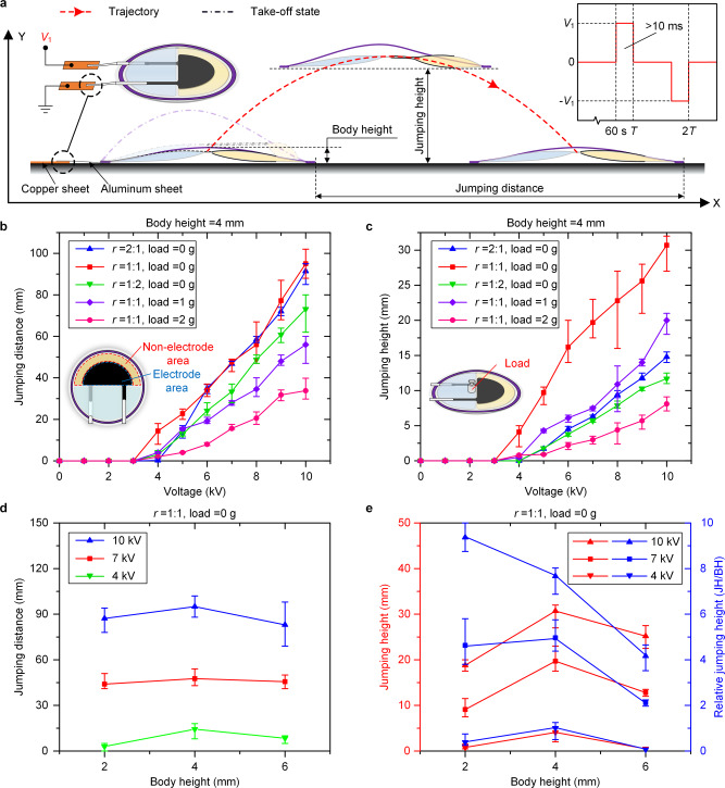
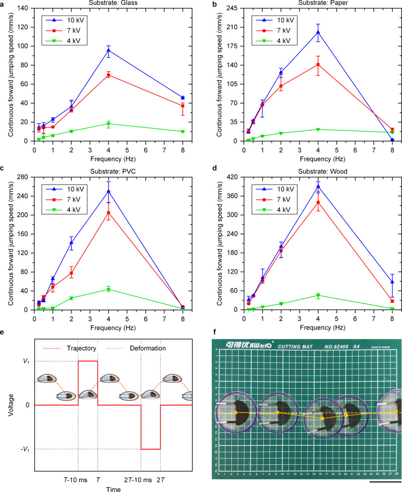
Jumping is an important locomotion function to extend navigation range, overcome obstacles, and adapt to unstructured environments. In that sense, continuous jumping and direction adjustability can be essential properties for terrestrial robots with multimodal locomotion. However, only few soft jumping robots can achieve rapid continuous jumping and controlled turning locomotion for obstacle crossing. Here, we present an electrohydrostatically driven tethered legless soft jumping robot capable of rapid, continuous, and steered jumping based on a soft electrohydrostatic bending actuator. This 1.1 g and 6.5 cm tethered soft jumping robot is able to achieve a jumping height of 7.68 body heights and a continuous forward jumping speed of 6.01 body lengths per second. Combining two actuator units, it can achieve rapid turning with a speed of 138.4° per second. The robots are also demonstrated to be capable of skipping across a multitude of obstacles. This work provides a foundation for the application of electrohydrostatic actuation in soft robots for agile and fast multimodal locomotion.


Conflict of interest statement

The authors declare no competing interests.

Figures

Fig. 1
Fig. 1. LSJR detailed design and motion principle.
a The LSJR consists of two plastic semicircular pouches printed with flexible electrodes. The front pouch is filled with a dielectric liquid, and the rear is filled with air with the same volume. A flexible plastic ring frame is fixed on the edge and is prestrained. Note that the rear air pouch functions to ensure that the pre-curved frame is consistent and maintains structural balance during the flight. b The LSJR prototype (1.1 g). Scale bar, 1 cm. c Schematic diagram of the LSJR jumping process. By the application of a high voltage to the two electrodes, the LSJR is energized to bend itself to generate forces and energy for forward jumping. During the voltage application, Maxwell stress squeezes the dielectric liquid and makes it flow laterally into the portion of the front pouch that is not covered by the electrodes (from the liquid outflow area to the liquid inflow area). d Cross-sectional views (e–e and f–f) of the LSJR: e–e denotes the deformation of the front pouch, whereas f–f shows the e–e deformation-driven whole-body bending and jumping. e Snapshots of the LSJR jumping, where 10 kV is applied to the actuator. Scale bar, 2 cm.
Fig. 2
Fig. 2. Single-jump characterization results.
See also Supplementary Movie 2. a Untethered single-jump process and parameters. The top left inset shows the electrical connections. The top right inset is the voltage application strategy in the experiment. b The relationship between JD and applied voltage under different loads (0, 1, and 2 g) and different electrode area/nonelectrode area ratios (2:1, 1:1, and 1:2). c The relationship between JH and applied voltage under different loads (0, 1, and 2 g) and different electrode area/nonelectrode area ratios (2:1, 1:1, and 1:2). d The relationship between JD and applied voltage at different body heights (2, 4, and 6 mm). e The relationship between JH, RJH, and applied voltage at different body heights (2, 4, and 6 mm).
Fig. 3
Fig. 3. Continuous jumping on different substrates.
See also Supplementary Movie 3. a The relationship between CFJS and actuation frequency on the glass plate, where the slowest average CFJS = 95.6 mm/s (1.47 body lengths per second) was obtained at 4 Hz and 10 kV. b The relationship between CFJS and actuation frequency on the paper plate. c The relationship between CFJS and actuation frequency on the PVC plate. d The relationship between CFJS and actuation frequency on the wood plate, where the fastest average CFJS = 390.5 mm/s (6.01 body lengths per second) was obtained at 4 Hz and 10 kV. e The voltage application strategy and the corresponding robot motion states. f Composite image of the initial position and four landing points in continuous jumping on the PVC plate when CFJS = 250.1 mm/s at 4 Hz and 10 kV. The angle deviation of each jump was less than 8°. Scale bar, 5 cm.
Fig. 4
Fig. 4. Turning results of the dual-body LSJR.
See also Supplementary Movie 4. a Schematic diagram of the dual-body LSJR turning process, which consists of the rest state, the turning state, and the landing state. Over each voltage cycle, the robot turns by an angle of α. b Center of gravity of the dual-body LSJR. c The relationship between TS and applied voltage on the four substrates. d Composite image of the initial and final positions during a continuous turning procedure on the PVC plate with a speed of 65.0°/s. The robot took 1.23 s to turn 80° at 10 kV and 4 Hz. Scale bar, 5 cm.
Fig. 5
Fig. 5. Single-unit LSJR obstacle crossing at 10 kV and 4 Hz.
See also Supplementary Movie 5. a Climbing on the glass plate (tilt angle of 3°) with a CFJS of 16.3 mm/s. b Crossing an electric wire (diameter of 6.3 mm). c Jumping across a square step (height of 8 mm). d Jumping across continuous steps (heights of 8 and 5 mm). Scale bar, 5 cm. e Composite image of the LSJR’s locomotion on a gravel mound (gravel size: 3–6 mm). Scale bar, 2 cm.
Fig. 6
Fig. 6. Dual-body LSJR obstacle crossing.
See also Supplementary Movie 6. a Straight jumping across a round step (height of 5 mm). b Steered jumping across the round step (height of 5 mm). c Jumping across a ring obstacle (height of 8 mm, inner diameter of 77 mm, and outer diameter of 83 mm). Scale bars, 10 cm.

Similar articles

Cited by

References

    1. Armour R, Paskins K, Bowyer A, Vincent J, Megill W. Jumping robots: a biomimetic solution to locomotion across rough terrain. Bioinspir. Biomim. 2007;2:S65. doi: 10.1088/1748-3182/2/3/S01. - DOI - PubMed
    1. Zhang Z, Zhao J, Chen H, Chen D. A survey of bioinspired jumping robot: takeoff, air posture adjustment, and landing buffer. Appl. Bionics Biomech. 2017;2017:1–22. doi: 10.1155/2017/4780160. - DOI - PMC - PubMed
    1. Zhang C, Zou W, Ma L, Wang Z. Biologically inspired jumping robots: a comprehensive review. Robot. Auton. Syst. 2020;124:103362. doi: 10.1016/j.robot.2019.103362. - DOI
    1. Kovač, M., Fuchs, M., Guignard, A., Zufferey, J. & Floreano, D. A miniature 7 g jumping robot. In IEEE International Conference on Robotics and Automation 373–378 (IEEE, 2008).
    1. Kovač M. The bioinspiration design paradigm: a perspective for soft robotics. Soft Robotics. 2014;1:28–37. doi: 10.1089/soro.2013.0004. - DOI

Publication types