. 2021 Nov 28;13(23):4164.
doi: 10.3390/polym13234164.

Icephobic and Anticorrosion Coatings Deposited by Electrospinning on Aluminum Alloys for Aerospace Applications

Affiliations

Icephobic and Anticorrosion Coatings Deposited by Electrospinning on Aluminum Alloys for Aerospace Applications

Adrián Vicente et al. Polymers (Basel). .

Abstract

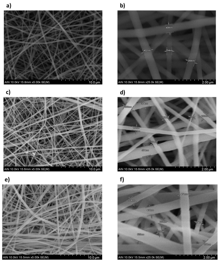
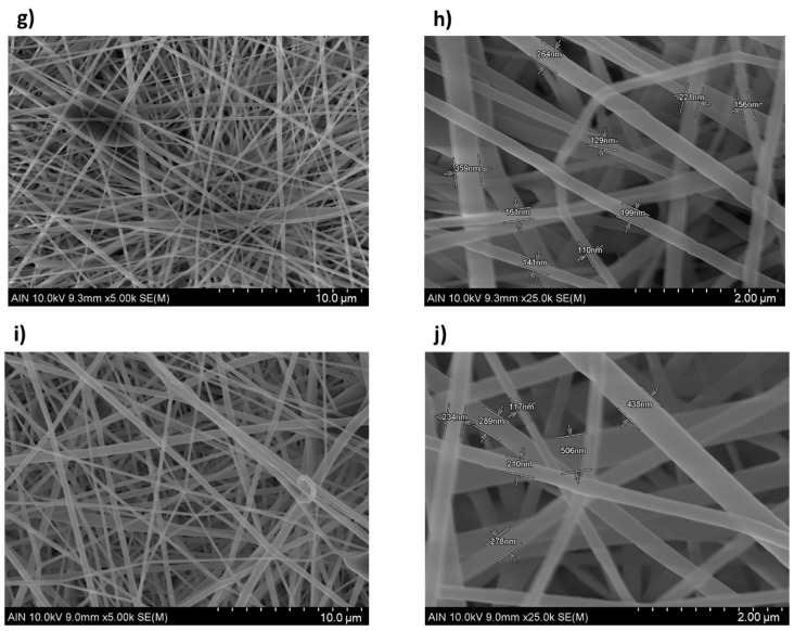
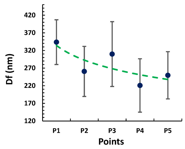
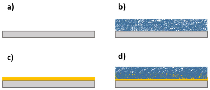
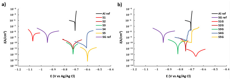
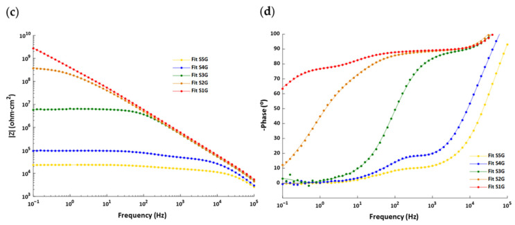
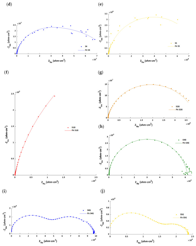
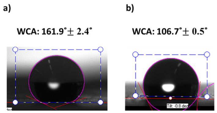
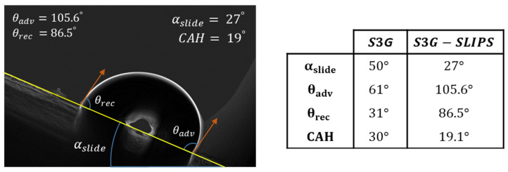
Anti-icing or passive strategies have undergone a remarkable growth in importance as a complement for the de-icing approaches or active methods. As a result, many efforts for developing icephobic surfaces have been mostly dedicated to apply superhydrophobic coatings. Recently, a different type of ice-repellent structure based on slippery liquid-infused porous surfaces (SLIPS) has attracted increasing attention for being a simple and effective passive ice protection in a wide range of application areas, especially for the prevention of ice formation on aircrafts. In this work, the electrospinning technique has been used for the deposition of PVDF-HFP coatings on samples of the aeronautical alloy AA7075 by using a thickness control system based on the identification of the proper combination of process parameters such as the flow rate and applied voltage. In addition, the influence of the experimental conditions on the nanofiber properties is evaluated in terms of surface morphology, wettability, corrosion resistance, and optical transmittance. The experimental results showed an improvement in the micro/nanoscale structure, which optimizes the superhydrophobic and anticorrosive behavior due to the air trapped inside the nanotextured surface. In addition, once the best coating was selected, centrifugal ice adhesion tests (CAT) were carried out for two types of icing conditions (glaze and rime) simulated in an ice wind tunnel (IWT) on both as-deposited and liquid-infused coatings (SLIPs). The liquid-infused coatings showed a low water adhesion (low contact angle hysteresis) and low ice adhesion strength, reducing the ice adhesion four times with respect to PTFE (a well-known low-ice-adhesion material used as a reference).

Keywords: PVDF-HFP; SLIPS; corrosion resistance; electrospinning; ice adhesion; super hydrophobic.


Conflict of interest statement

The authors declare no conflict of interest.

Figures

Figure 1
Figure 1
EIS circuit setup. Counter electrode current (Ice), reference electrode (Re), working electrode (We), ground electrode (GNDe), and circuit impedance (Z).
Figure 2
Figure 2
Test section of the icing wind tunnel (IWT) in a cold climate chamber at INTA, Spain.
Figure 3
Figure 3
The ice was accreted in one half of the area of the 50 × 50 mm2 samples using a mask to have an iced area of 12.5 cm2.
Figure 4
Figure 4
Centrifuge adhesion test (CAT) on a rotatory beam.
Figure 5
Figure 5
Operating diagram for PVDF-HFP, electrospinning jet modes: the dripping region delimited with the cone jet region by Vmin and the oscillating jet region delimited with the cone jet region by Vmax. Within the cone jet area, there are five selected samples-points to study: P1 (13.2 KV; 500 µL/h), P2 (15.5 KV; 1000 µL/h), P3 (17.7 KV; 2000 µL/h), P4 (19.5 KV; 3000 µL/h), and P5 (20.5 KV; 4000 µL/h).
Figure 6
Figure 6
Schematic diagram of main electrospinning modes: (a) dripping mode, (b) cone jet mode, (c) oscillating mode, and (d) multi-jet mode.
Figure 7
Figure 7
Evolution of the thickness as a function of the deposition time for different operating conditions of flow rate and applied voltage.
Figure 8
Figure 8
(a) 3D confocal image of the cross-section S3 sample, where a restore algorithm and a vertical profile have been selected. (b) 2D image of the vertical profile with the step function measurement.
Figure 9
Figure 9
(a) Evolution of the average surface roughness (Sa) as a function of the operational points (P1, P2, P3, P4, and P5). 3D images representing the surface morphology of the electrospun mats in sample S3 (2000 µL/h and 17.7 KV) with the (b) confocal microscope and AFM (c,d) in the scale of 75 µm and 10 µm, respectively.
Figure 10
Figure 10
Scanning electron microscopy (SEM) images representing the surface morphology of the electrospun mats for sample S1 (a,b) (500 µL/h and 13.2 KV), S2 (c,d) (1000 µL/h and 15.3 KV), S3 (e,f) (2000 µL/h and 17.7 KV), S4 (g,h) (3000 µL/h and 19.5 KV), and sample S5 (i,j) (5000 µL/h and 20.5 KV) at the scale of 10 µm (a,c,e,g,i) and 2 µm (b,d,f,h,j), respectively.
Figure 10
Figure 10
Scanning electron microscopy (SEM) images representing the surface morphology of the electrospun mats for sample S1 (a,b) (500 µL/h and 13.2 KV), S2 (c,d) (1000 µL/h and 15.3 KV), S3 (e,f) (2000 µL/h and 17.7 KV), S4 (g,h) (3000 µL/h and 19.5 KV), and sample S5 (i,j) (5000 µL/h and 20.5 KV) at the scale of 10 µm (a,c,e,g,i) and 2 µm (b,d,f,h,j), respectively.
Figure 11
Figure 11
Evolution of the fiber diameter (Df) and its standard deviation as a function of the operational points (P1, P2, P3, P4, and P5).
Figure 12
Figure 12
FTIR spectrum of the PVDF-co-HFP electrospun fibers.
Figure 13
Figure 13
(a) Evolution of the water contact angle (WCA) and its standard deviation as a function of the operational points (P1, P2, P3, P4, and P5). (b) Behavior of the WCA as a function of the average surface roughness (Sa).
Figure 14
Figure 14
(a) Aluminum alloy substrates (AA7075-T6). (b) Aluminum substrate and electrospun layer. (c) Aluminum substrate with glue layer. (d) Aluminum substrate with glue layer and electrospun layer.
Figure 15
Figure 15
Tafel plots corresponding to the aluminum bare substrate and the different aluminum samples composed of PVDF-HFP electrospun fibers mats without (a) and with (b) glue layer after being tested in 6 wt% NaCl aqueous solution. For greater clarity, only the interval ±100 mV is shown in each curve.
Figure 16
Figure 16
Bode diagrams corresponding to the S1–S5 samples: (a) modulus and (b) frequencies as well as those corresponding to the S1G–S5G samples: (c) modulus and (d) frequencies.
Figure 16
Figure 16
Bode diagrams corresponding to the S1–S5 samples: (a) modulus and (b) frequencies as well as those corresponding to the S1G–S5G samples: (c) modulus and (d) frequencies.
Figure 17
Figure 17
Nyquist plots corresponding to the samples (a) S1, (b) S2, (c) S3, (d) S4, (e) S5, (f) S1G, (g) S2G, (h) S3G, (i) S4G, and (j) S5G.
Figure 17
Figure 17
Nyquist plots corresponding to the samples (a) S1, (b) S2, (c) S3, (d) S4, (e) S5, (f) S1G, (g) S2G, (h) S3G, (i) S4G, and (j) S5G.
Figure 18
Figure 18
Diagram of the equivalent circuit for a damaged coating. Counter electrode current (Ice), reference electrode (Re), working electrode (We), ground electrode (GNDe), circuit impedance (Z), resistance of the electrolyte solution (Rs), the pore resistance (Rpore), the charge transfer resistance (Rct), the constant phase elements of the coating (ZCPE coating), and the constant phase elements of the doble layer (ZCPE dl).
Figure 19
Figure 19
Static water contact angles (WCA) of samples S3G (a) and S3G-SLIPS (b). The sample S3G (a) exhibits a superhydrophobic behavior (WCA < 150°) and samples S3G-SLIPS (b) a hydrophobic behavior (90° < WCA < 150°).
Figure 20
Figure 20
The sliding water angles (αslide), the advancing contact angle (θadv), the receding contact angle (θrec), and the contact angle of hysteresis (CAH) of the S3G and S3G-SLIPS samples.
Figure 21
Figure 21
(a) Transmittance Vis-NIR spectra of the SHS and SLIPS samples. (b) Reflectance Vis-NIR spectra of the SHS and SLIPS samples. (c) The resultant SHS and SLIPS appearance.
Figure 22
Figure 22
Graphs of ice adhesion tests after glaze and rime icing procedures in IWT.
Figure 23
Figure 23
Graphs of the adhesion reduction factor of several coatings: aluminum substrate, PTFE, S3G, and S3G-SLIPS.

References

    1. Bolgiani P., Fernández-González S., Martin M.L., Valero F., Merino A., García-Ortega E., Sánchez J.L. Analysis and numerical simulation of an aircraft icing episode near Adolfo Suárez Madrid-Barajas International Airport. Atmos. Res. 2018;200:60–69. doi: 10.1016/j.atmosres.2017.10.001. - DOI
    1. Carriveau R., Edrisy A., Cadieux P., Mailloux R. Ice Adhesion Issues in Renewable Energy Infrastructure. J. Adhes. Sci. Technol. 2012;26:447–461. doi: 10.1163/016942411X574592. - DOI
    1. Laforte J.L., Allaire M.A., Laflamme J. State-of-the-art on power line de-icing. Atmos. Res. 1998;46:143–158. doi: 10.1016/S0169-8095(97)00057-4. - DOI
    1. Shao Z., Wang Y., Bai H. A superhydrophobic textile inspired by polar bear hair for both in air and underwater thermal insulation. Chem. Eng. J. 2020;397:125441. doi: 10.1016/j.cej.2020.125441. - DOI
    1. Giacomello A., Meloni S., Chinappi M., Casciola C.M. Cassie–Baxter and Wenzel States on a Nanostructured Surface: Phase Diagram, Metastabilities, and Transition Mechanism by Atomistic Free Energy Calculations. Langmuir. 2012;28:10764–10772. doi: 10.1021/la3018453. - DOI - PubMed