. 2021 Nov 26:12:100166.
doi: 10.1016/j.mtbio.2021.100166. eCollection 2021 Sep.

Electrostatic flocking of salt-treated microfibers and nanofiber yarns for regenerative engineering

Affiliations

Electrostatic flocking of salt-treated microfibers and nanofiber yarns for regenerative engineering

Alec McCarthy et al. Mater Today Bio. .

Abstract

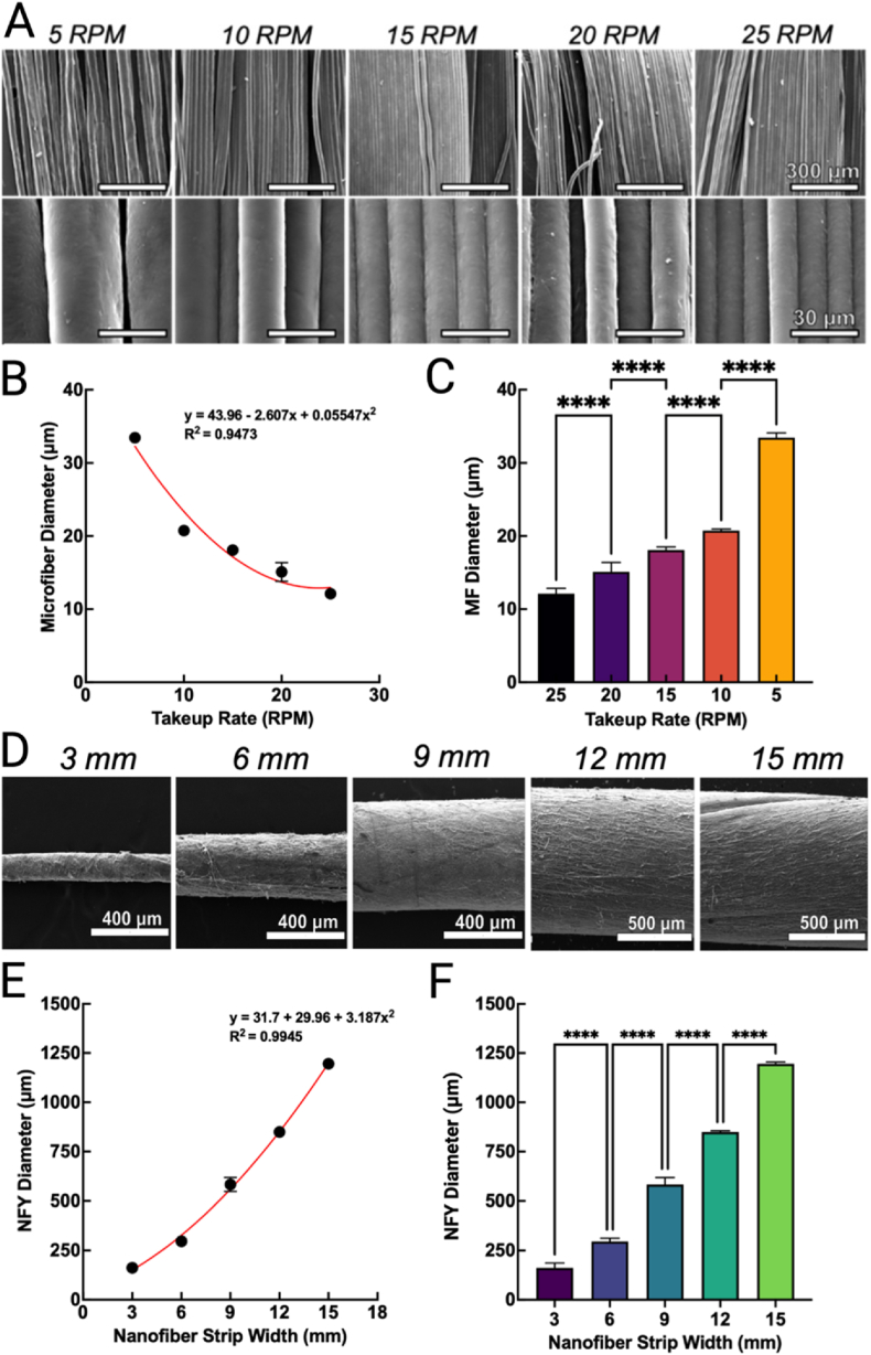
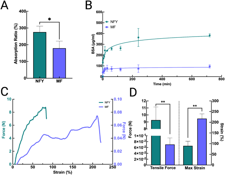
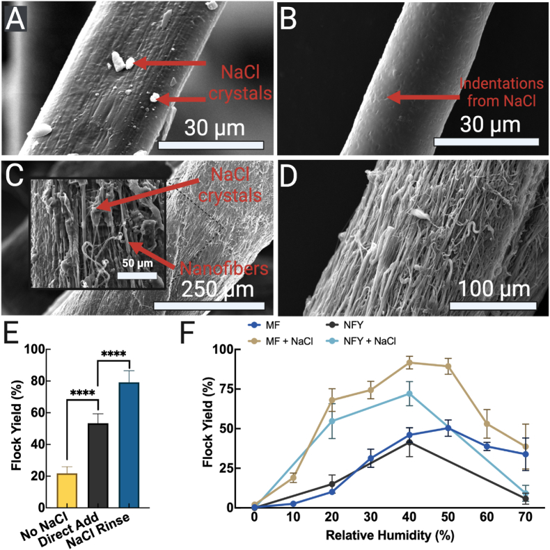
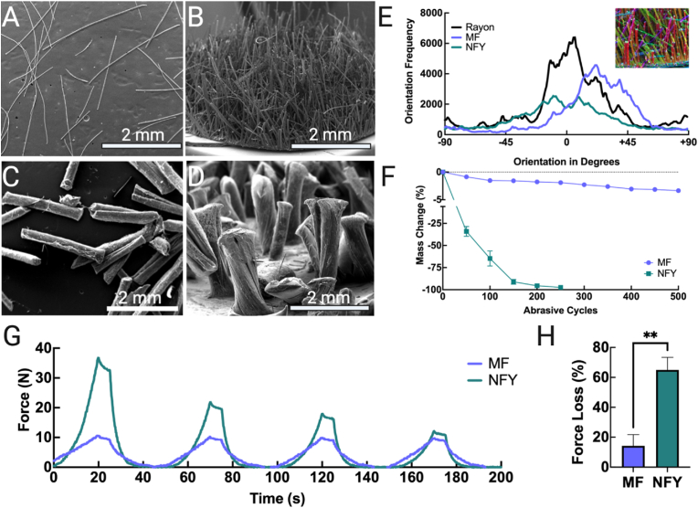
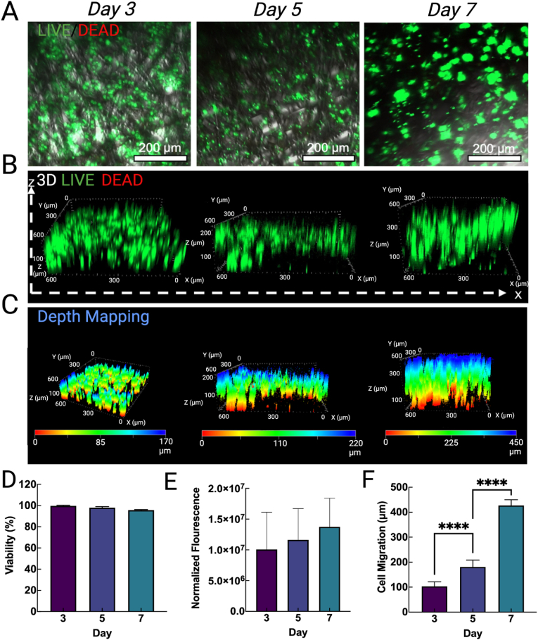
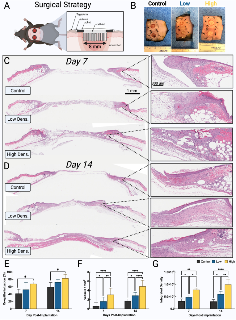
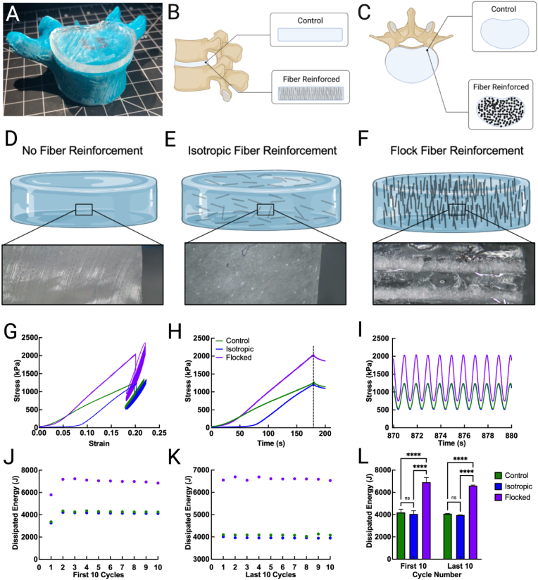
Electrostatic flocking is a textile technology that employs a Coulombic driving force to launch short fibers from a charging source towards an adhesive-covered substrate, resulting in a dense array of aligned fibers perpendicular to the substrate. However, electrostatic flocking of insulative polymeric fibers remains a challenge due to their insufficient charge accumulation. We report a facile method to flock electrostatically insulative poly(ε-caprolactone) (PCL) microfibers (MFs) and electrospun PCL nanofiber yarns (NFYs) by incorporating NaCl during pre-flock processing. Both MF and NFY were evaluated for flock functionality, mechanical properties, and biological responses. To demonstrate this platform's diverse applications, standalone flocked NFY and MF scaffolds were synthesized and evaluated as scaffold for cell growth. Employing the same methodology, scaffolds made from poly(glycolide-co-l-lactide) (PGLA) (90:10) MFs were evaluated for their wound healing capacity in a diabetic mouse model. Further, a flock-reinforced polydimethylsiloxane (PDMS) disc was fabricated to create an anisotropic artificial vertebral disc (AVD) replacement potentially used as a treatment for lumbar degenerative disc disease. Overall, a salt-based flocking method is described with MFs and NFYs, with wound healing and AVD repair applications presented.

Keywords: Artificial vertebral disc; Electrostatic flocking; Microfibers; Nanofiber yarns; Wound healing.


Conflict of interest statement

The authors declare that they have no known competing financial interest or personal relationships that could have appeared to influence the work reported in this paper.

Figures

Image 1
Graphical abstract
Fig. 1
Fig. 1
Schematic illustrating the fabrication of scaffolds by electrostatic flocking for potential biomedical applications. (A) Microfibers fabricated by wet spinning. (B) Electrospun nanofiber yarns fabricated by cutting and rolling. (C) NaCl treatment. (D) Electrostatic flocking and obtained scaffolds for cell growth, wound healing, and artificial vertebral disc replacement.
Fig. 2
Fig. 2
Optimization of fiber fabrication. (A) SEM images of PCL microfibers prepared at increased take-up rates. (B) Curve-fit for microfiber diameter estimation for wet spinning. (C) Comparison of average microfiber diameters. (D) SEM images of nanofiber yarns rolled from different diameter nanofiber strips. (E) Curve-fit guide for nanofiber yarn diameter estimation. (F) Comparison of average nanofiber yarn diameters. NFY: nanofiber yarns.
Fig. 3
Fig. 3
Characterization of microfibers and nanofiber yarns. (A) Absorption ratios of each fiber type after immersion in a BSA solution. (B) BSA release profiles of each fiber type. (C) Force-displacement curves of each fiber type. (D) Maximum break forces and maximum strains of each fiber type. NFY: nanofiber yarns. MF: microfibers.
Fig. 4
Fig. 4
Introduction of salt via salt bath washing increases flocking yields over a range of relative humidity. (A) SEM image of a salt-covered (red arrows) microfiber (MF) after flocking. (B) SEM image of a flock fiber after washing with H2O. (C) SEM of a salt-covered nanofiber yarn (NFY) after flocking and (D) after rinsing with H2O. (E) The flock yield of MFs prepared with two different salt implementing strategies and (F) the resulting yield of NaCl-rinsed and untreated MFs and NFYs at a range of humidities.
Fig. 5
Fig. 5
Flock fibers and scaffold characterization. (A) SEM images of microfibers (MFs) and (B) flocked MF scaffolds. (C) SEM images of nanofiber yarns (NFYs) and (D) flocked NFY scaffolds. (E) Anisotropy measurements of rayon (control), MFs, and NFYs (colored image shows the tensor analysis of MF scaffolds used to plot orientation curves. (F) Mass loss from abrasive cycles of MFs and NFYs during rub testing. (G) Compression curves of NFY and MF scaffolds undergoing 50% displacement and (H) average compressive force lost between the first and fourth compressive cycle.
Fig. 6
Fig. 6
HaCaT proliferation and migration. (A) Live/Dead ​+ ​DIC confocal images of HaCaT cells cultured on salt-treated PCL MF flocked scaffolds for 3, 5, and 7 days. (B) Normalized viability over the 7-day culture period. (C) 3D Live/Dead images showing cell distribution throughout the flocked scaffolds. (D) Normalized fluorescence intensity of HaCaT-seeded scaffolds at 3, 5, and 7 days. (E) Depth mapping of HaCaTs on the flocked scaffolds at 3, 5, and 7 days and (F) their related leading average cell migration measurements.
Fig. 7
Fig. 7
Low- and high-density flocked scaffolds for wound healing. (A) Surgical strategy schematic. Flock fibers are positioned facing the wound bed and the chitosan/gelatin substrate is flush with the wound edge. Splints are glued and sutured into place to prevent wound contraction. (C, D) H&E staining of wounds after 7 and 14 days of no treatment, low-density flock scaffold treatment, and high-density flock scaffold treatment. (E) Re-epithelialization measured as the fraction of epithelium over the defect site. (F) New vessels formed within the wounds. (G) Collagen deposition within the wound measured via integrated density in color-split trichrome stained images. Control: without treatment; Low: low-density flocked scaffolds; High: high-density flocked scaffolds.
Fig. 8
Fig. 8
Mechanical analysis of artificial vertebral disc (AVD) undergoing cyclic compressive loads. (A) Photograph of AVD situated on L5 model during sizing. (B, C) Representative (B) side and (C) top view of AVD in situ. (D–F) Schematic and cross-sectional microscopic image of (D) pure PDMS AVD, (E) isotropic fiber-reinforced AVD, and (F) flock fiber reinforced AVD. (G) Full stress-strain curve of each AVD model. (H) Stress curves during the first 3 ​min of compression (ramping). (I) Last 10 cyclic compressive loads to display waveform stress recovery. (J–L) Dissipation energy during (J) the first 10 and (K) last 10 compressive cycles and (L) their change between cycle sets.

References

    1. Fang Y., Xu Y., Wang Z., Zhou W., Yan L., Fan X., Liu H. 3D porous chitin sponge with high absorbency, rapid shape recovery, and excellent antibacterial activities for noncompressible wound. Chem. Eng. J. 2020;388:124169. doi: 10.1016/j.cej.2020.124169. - DOI
    1. Chen S., Wang H., McCarthy A., Yan Z., Kim H.J., Carlson M.A., Xia Y., Xie J. Three-dimensional objects consisting of hierarchically assembled nanofibers with controlled alignments for regenerative medicine. Nano Lett. 2019;19:2059–2065. doi: 10.1021/acs.nanolett.9b00217. - DOI - PubMed
    1. John J.V., McCarthy A., Wang H., Luo Z., Li H., Wang Z., Cheng F., Zhang Y.S., Xie J. Freeze-casting with 3D-printed templates creates anisotropic microchannels and patterned macrochannels within biomimetic nanofiber aerogels for rapid cellular infiltration. Adv. Healthc. Mater. 2021;12:2100238. doi: 10.1002/adhm.202100238. - DOI - PMC - PubMed
    1. Wang C., Chen X., Wang B., Huang M., Wang B., Jiang Y., Ruoff R.S. Freeze-casting produces a graphene oxide aerogel with a radial and centrosymmetric structure. ACS Nano. 2018;12:5816–5825. doi: 10.1021/acsnano.8b01747. - DOI - PubMed
    1. Balasubramanian P., Boccaccini A.R. Bilayered bioactive glass scaffolds incorporating fibrous morphology by flock technology. Mater. Lett. 2015;158:313–316. doi: 10.1016/j.matlet.2015.06.036. - DOI

LinkOut - more resources