. 2021 Dec 14;12(1):7238.
doi: 10.1038/s41467-021-27317-1.

A low-cost and shielding-free ultra-low-field brain MRI scanner

Affiliations

A low-cost and shielding-free ultra-low-field brain MRI scanner

Yilong Liu et al. Nat Commun. .

Abstract

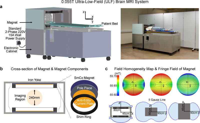
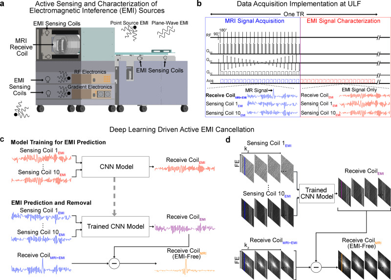
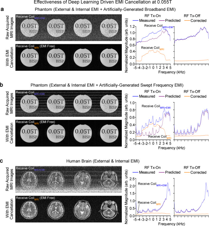
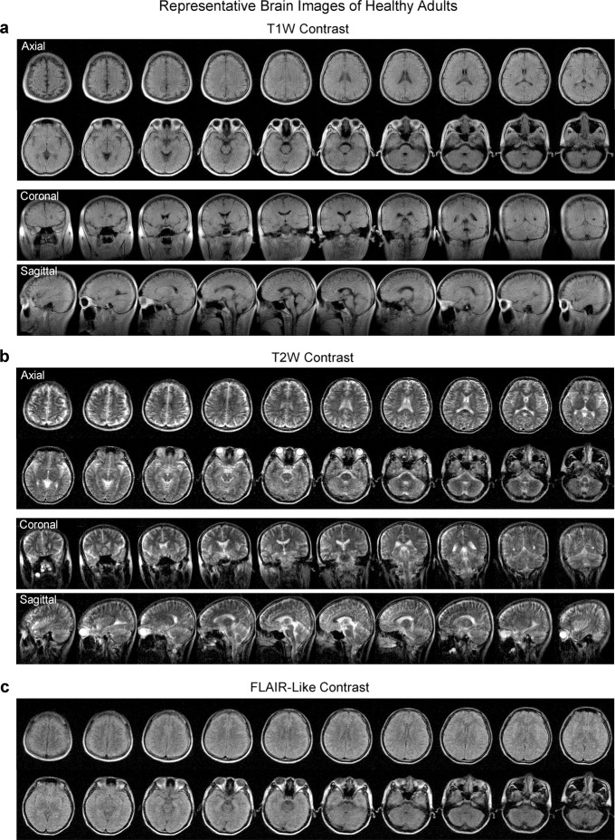
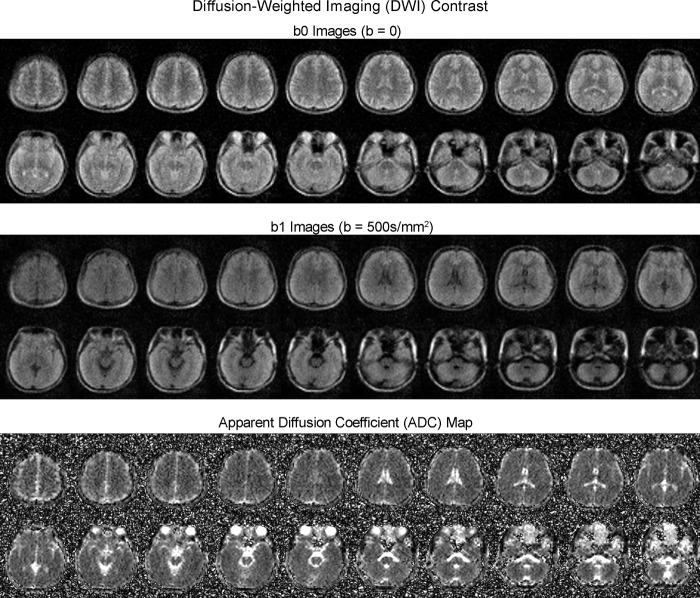
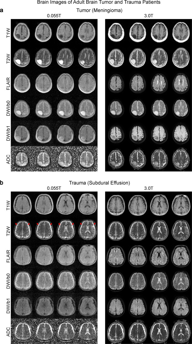
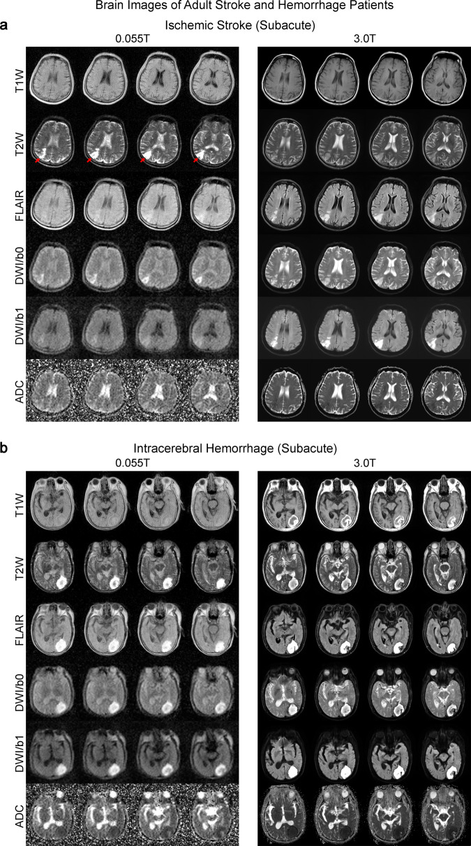
Magnetic resonance imaging is a key diagnostic tool in modern healthcare, yet it can be cost-prohibitive given the high installation, maintenance and operation costs of the machinery. There are approximately seven scanners per million inhabitants and over 90% are concentrated in high-income countries. We describe an ultra-low-field brain MRI scanner that operates using a standard AC power outlet and is low cost to build. Using a permanent 0.055 Tesla Samarium-cobalt magnet and deep learning for cancellation of electromagnetic interference, it requires neither magnetic nor radiofrequency shielding cages. The scanner is compact, mobile, and acoustically quiet during scanning. We implement four standard clinical neuroimaging protocols (T1- and T2-weighted, fluid-attenuated inversion recovery like, and diffusion-weighted imaging) on this system, and demonstrate preliminary feasibility in diagnosing brain tumor and stroke. Such technology has the potential to meet clinical needs at point of care or in low and middle income countries.


Conflict of interest statement

The authors declare no competing interests.

Figures

Fig. 1
Fig. 1. Prototype of a low-cost low-power and shielding-free brain ultra-low-field (ULF) magnetic resonance imaging (MRI) scanner with homogenous 0.055 Tesla magnetic field and small 5 Gauss fringe field.
a With ~2 m2 footprint and no radiofrequency/magnetic shielding cages, the scanner can be mobile and located on any building floor with no special siting requirements. It operates from only a standard alternating current (AC) wall power outlet (50 Hz 2-phase 220 V 15 A). b The 0.055 T magnet utilizes an iron yoke, samarium-cobalt (SmCo) plates, polar pieces, anti-eddy current plates and passive shimming rings, and with adequate opening for patient chest and shoulder (29 cm vertical gap and 70 cm width). c The magnet provides a homogeneity <2000 ppm peak-to-peak over 240 mm diameter of spherical volume (DSV), which can be reduced to <250 ppm after additional passive shimming. The 5 Gauss fringe field is within 45 cm, 90 cm, and 80 cm in X, Y and Z directions from magnet center.
Fig. 2
Fig. 2. Deep learning driven detection and cancellation of electromagnetic interference (EMI) signals for low-cost 0.055 T MRI without radiofrequency (RF) shielding.
a Ten small RF coils, i.e., EMI sensing coils, are strategically placed in the vicinity of transmit and receive RF coils, underneath the patient bed, and inside electronic cabinet to actively detect EMI signals only that are from both external environments and internal electronics. b Illustration of the 3D fast spin echo (FSE) pulse sequence data acquisition for both MRI signal collection and EMI signal characterization. Within each time of repetition (TR), data are acquired simultaneously by both MRI receive coil and EMI sensing coils across within two windows—the conventional MRI signal acquisition window and the EMI signal characterization window. Note that MRI signal is zero within EMI signal characterization window. c After each scan, a convolutional neural network (CNN) model is trained to establish the relationship between the EMI signals received by MRI receive coil and the sensing coils within EMI signal characterization window. The trained model can then predict the EMI signal component detected by the MRI receive coil within the MRI signal acquisition window from the simultaneously detected signals by EMI sensing coils for each frequency encoding (FE) line. The predicted EMI is subtracted from MRI receive coil signal to produce the EMI-free FE line. d This procedure is repeated for all individual FE lines before averaging and subsequent image reconstruction from the EMI-free k-space data.
Fig. 3
Fig. 3. Robust deep learning driven EMI cancellation for 0.055 T phantom and brain imaging without RF shielding in the presence of various external or internal EMI sources.
Representative 3D FSE T2-weighted (T2W) images (left) and corresponding magnitude averaged spectra (right) of raw MRI FE lines, before and after EMI elimination, with RF transmit (Tx) power on (i.e., producing MRI signals) or off (i.e., no MRI signal, EMI signals only) for a phantom with a broadband EMI generated from a nearby source, b phantom with a swept frequency EMI generated from a nearby source, and c human brain (23 yrs. old; male). The proposed deep learning EMI elimination technique can robustly predict the EMI signals detected by the MRI receive coil, enabling MRI scan without any RF cage or shield. Note that, during brain scanning, the large human body acts as an antenna that receives high level of external environmental EMI signals, which can still be effectively eliminated by the technique.
Fig. 4
Fig. 4. Typical brain images from healthy adults produced by the low-cost and shielding-free 0.055 T MRI scanner.
Whole-brain axial, coronal and sagittal sections of the brain were acquired at two common contrasts, namely a T1-weighted (T1W) images using the 3D gradient-echo sequence and b T2W using 3D fast spin echo sequence. c Whole-brain axial sections acquired with fluid-attenuated inversion recovery (FLAIR) like contrast using the 3D FSE sequence with short TR. Scan times are 5.5 mins, 7.5 mins and 7.5 mins for T1W, T2W and FLAIR protocols, respectively. All images are displayed at a spatial resolution of 1 × 1 × 5 mm3, while the acquisition resolution is approximately 2 × 2 × 10 mm. The axial (23 yrs. old; male) and coronal/sagittal (23 yrs. old; male) images shown here were acquired from two healthy adults, respectively.
Fig. 5
Fig. 5. Typical diffusion-weighted imaging (DWI) images (from a healthy adult) produced by the low-cost and shielding-free 0.055 T MRI scanner.
Whole-brain axial sections (23 yrs. old; male) using the 2D echo-planar imaging DWI sequence with isotropic diffusion weighting factor b-value = 0 (b0 images) and 500 s/mm2 (b1 images). Apparent diffusion coefficient (ADC) maps are also shown. Total scan time is 9.5 mins. All images are displayed at a spatial resolution of 1 × 1 × 5 mm3 while the acquisition resolution is approximately 4 × 4 × 10 mm3.
Fig. 6
Fig. 6. Clinical utility of 0.055 T MRI for examining tumor and trauma patients.
Total scan time was ~30 mins for T1W, T2W, FLAIR and DWI protocols for each patient at 0.055 T. Both patients were scanned by 3 T MRI on the same day using the standard T1W, T2W, FLAIR and DWI brain protocols (~20 mins total scan time) for comparison. a Patient (75 yrs. old; female) with an extra-axial mass (i.e., meningioma) at the right parietal cortex. Both 0.055 T and 3 T images showed that the tumor mass was hypointense in T1W and hyperintense in T2W. b Patient (64 yrs. old; male) with subdural effusion (i.e., collection of cerebrospinal fluid, CSF, trapped between the surface of the brain and the dura matter) due to previous head trauma. The subdural collection with sulci obliteration showing as a bright signal in T2W images (indicated by red arrows) was visible at bilateral fronto-parietal regions.
Fig. 7
Fig. 7. Clinical utility of 0.055 T MRI for examining ischemic stroke and intracerebral hemorrhage (ICH) patients.
Total 0.055 T scan time was ~30 mins for each patient. The patients were also scanned by a clinical 3 T MRI using the standard clinical protocols (~20 mins total scan time). a Subacute (~3 weeks) ischemic stroke patient (67 yrs. old; male). Note that 3 T clinical brain images were acquired 3 weeks prior to those acquired at 0.055 T. Ischemic infarct in the right parietal cortex (indicated by red arrows) was hyperintense in T2 and FLAIR images at 0.055 T and 3 T. Further, infarct was mildly hyperintense at ULF DWI, whereas it was hyperintense at 3 T. ADC showed slight hyperintensity at 0.055 T and hypointensity at 3 T. The corresponding signal changes for DWI and ADC maps at 0.055 T and 3 T are highly consistent with the expected progression of ischemic stroke across different timepoints (i.e., subacute vs. acute). b Subacute (~3 weeks) ICH patient (81 yrs. old; male). 0.055 T and 3 T images were acquired on the same day. Hematoma was visible in the left occipital lobe at 0.055 T and 3 T. It showed a hyperintense rim with a hypointense core in T2W images, indicating blood product and/or hemosiderin of different stages at the rim and core regions.
Fig. 8
Fig. 8. Low sensitivity to commonly used clinical metal implants at 0.055 T.
Illustration of metal implants (left) and corresponding images acquired at 0.055 T (right) of a titanium alloy aneurysm clips and, b cerebrovascular stents with three distinct types of metal alloys. Metal-induced image artifacts were dramatically reduced at 0.055 T. Almost no visible artifacts were present around the titanium alloy metal clips and the nickel-titanium alloy stent. Slight artifacts were visible in the images for the cobalt-platinum alloy and stainless-steel stents (indicated by red arrows). These implants were immersed in water and imaged with the 3D axial GRE and FSE sequences with FE direction along horizontal or vertical direction. Note that the main field 0.055 T was along the vertical direction.

References

    1. Fuchs VR, Sox HC., Jr. Physicians’ views of the relative importance of thirty medical innovations. Health Aff. 2001;20:30–42. - PubMed
    1. Magnetic resonance imaging (MRI) exams (indicator). Vol. 2021 (OECD).
    1. Reimer, P. Clinical MR imaging: a practical approach (Springer, Berlin, 2010).
    1. Nowogrodzki A. The world’s strongest MRI machines are pushing human imaging to new limits. Nature. 2018;563:24–26. - PubMed
    1. Bornert P, Norris DG. A half-century of innovation in technology-preparing MRI for the 21st century. Br. J. Radio. 2020;93:20200113. - PMC - PubMed

Publication types