

3D printing and continuous flow chemistry technology to advance pharmaceutical manufacturing in developing countries
- PMID: 34909056
- PMCID: PMC7511217
- DOI: 10.1016/j.arabjc.2020.09.020
3D printing and continuous flow chemistry technology to advance pharmaceutical manufacturing in developing countries
Abstract
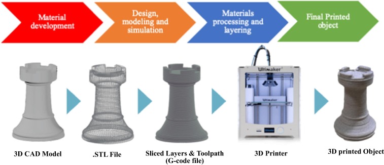
The realization of a downward spiralling of diseases in developing countries requires them to become self-sufficient in pharmaceutical products. One of the ways to meet this need is by boosting the local production of active pharmaceutical ingredients and embracing enabling technologies. Both 3D printing and continuous flow chemistry are being exploited rapidly and they are opening huge avenues of possibilities in the chemical and pharmaceutical industries due to their well-documented benefits. The main barrier to entry for the continuous flow chemistry technique in low-income settings is the cost of set-up and maintenance through purchasing of spare flow reactors. This review article discusses the technical considerations for the convergence of state-of-the-art technologies, 3D printing and continuous flow chemistry for pharmaceutical manufacturing applications in developing countries. An overview of the 3D printing technique and its application in fabrication of continuous flow components and systems is provided. Finally, quality considerations for satisfying regulatory requirements for the approval of 3D printed equipment are underscored. An in-depth understanding of the interrelated aspects in the implementation of these technologies is crucial for the realization of sustainable, good quality chemical reactionware.
Keywords: 3D printing; Affordable; Continuous flow chemistry; Developing countries; Pharmaceutical manufacturing; Quality control.
© 2020 The Author(s).
Conflict of interest statement
The authors declare that they have no known competing financial interests or personal relationships that could have appeared to influence the work reported in this paper.
Figures


Similar articles
-
Additive Manufacturing with 3D Printing: Progress from Bench to Bedside.AAPS J. 2018 Sep 12;20(6):101. doi: 10.1208/s12248-018-0225-6. AAPS J. 2018. PMID: 30209693 Review.
-
A new chapter in pharmaceutical manufacturing: 3D-printed drug products.Adv Drug Deliv Rev. 2017 Jan 1;108:39-50. doi: 10.1016/j.addr.2016.03.001. Epub 2016 Mar 18. Adv Drug Deliv Rev. 2017. PMID: 27001902 Review.
-
Achieving continuous manufacturing: technologies and approaches for synthesis, workup, and isolation of drug substance. May 20-21, 2014 Continuous Manufacturing Symposium.J Pharm Sci. 2015 Mar;104(3):781-91. doi: 10.1002/jps.24252. Epub 2014 Dec 2. J Pharm Sci. 2015. PMID: 25470351 Review.
-
3D printing: Principles and pharmaceutical applications of selective laser sintering.Int J Pharm. 2020 Aug 30;586:119594. doi: 10.1016/j.ijpharm.2020.119594. Epub 2020 Jul 2. Int J Pharm. 2020. PMID: 32622811 Review.
-
Additive Manufacturing of Solid Products for Oral Drug Delivery Using Binder Jetting Three-Dimensional Printing.AAPS PharmSciTech. 2022 Jul 14;23(6):196. doi: 10.1208/s12249-022-02321-w. AAPS PharmSciTech. 2022. PMID: 35835970 Review.
Cited by
-
A field guide to flow chemistry for synthetic organic chemists.Chem Sci. 2023 Mar 15;14(16):4230-4247. doi: 10.1039/d3sc00992k. eCollection 2023 Apr 26. Chem Sci. 2023. PMID: 37123197 Free PMC article. Review.
-
Efficient photocatalytic reactors via 3D printing: SLA fabrication and TiO2 hybrid materials.RSC Adv. 2025 Jan 23;15(4):2275-2286. doi: 10.1039/d4ra07121b. eCollection 2025 Jan 23. RSC Adv. 2025. PMID: 39867337 Free PMC article.
-
A miniaturized 3D printed pressure regulator (µPR) for microfluidic cell culture applications.Sci Rep. 2022 Jun 24;12(1):10769. doi: 10.1038/s41598-022-15087-9. Sci Rep. 2022. PMID: 35750792 Free PMC article.
-
Freeform generative design of complex functional structures.Sci Rep. 2024 May 24;14(1):11918. doi: 10.1038/s41598-024-62830-5. Sci Rep. 2024. PMID: 38789601 Free PMC article.
References
-
- Aguiar R.M., Leão R.A.C., Mata A., Cantillo D., Kappe C.O., Miranda L.S.M., De Souza R.O.M.A. Continuous-flow protocol for the synthesis of enantiomerically pure intermediates of anti epilepsy and anti tuberculosis active pharmaceutical ingredients. Org. Biomol. Chem. 2019;17:1552–1557. doi: 10.1039/C8OB03088J. - DOI - PubMed
Publication types
LinkOut - more resources
Full Text Sources