. 2022 Feb 15:247:118818.
doi: 10.1016/j.neuroimage.2021.118818. Epub 2021 Dec 14.

Cross-Axis projection error in optically pumped magnetometers and its implication for magnetoencephalography systems

Affiliations

Cross-Axis projection error in optically pumped magnetometers and its implication for magnetoencephalography systems

Amir Borna et al. Neuroimage. .

Abstract

Optically pumped magnetometers (OPMs) developed for magnetoencephalography (MEG) typically operate in the spin-exchange-relaxation-free (SERF) regime and measure a magnetic field component perpendicular to the propagation axis of the optical-pumping photons. The most common type of OPM for MEG employs alkali atoms, e.g. 87Rb, as the sensing element and one or more lasers for preparation and interrogation of the magnetically sensitive states of the alkali atoms ensemble. The sensitivity of the OPM can be greatly enhanced by operating it in the SERF regime, where the alkali atoms' spin exchange rate is much faster than the Larmor precession frequency. The SERF regime accommodates remnant static magnetic fields up to ±5 nT. However, in the presented work, through simulation and experiment, we demonstrate that multi-axis magnetic signals in the presence of small remnant static magnetic fields, not violating the SERF criteria, can introduce significant error terms in OPM's output signal. We call these deterministic errors cross-axis projection errors (CAPE), where magnetic field components of the MEG signal perpendicular to the nominal sensing axis contribute to the OPM signal giving rise to substantial amplitude and phase errors. Furthermore, through simulation, we have discovered that CAPE can degrade localization and calibration accuracy of OPM-based magnetoencephalography (OPM-MEG) systems.

Keywords: CAPE; Cross-axis projection error; MEG; Magnetoencephalography; OPM; OPM-MEG; Source localization.


Conflict of interest statement

Declaration of Competing Interest The authors declare that they have no known competing financial interests or personal relationships that could have appeared to influence the work reported in this paper.

Figures

Fig. 1.
Fig. 1.
The OPM sensor’s coordinates. Circularly (linearly)-polarized pump (probe)-beam are coaligned on the z-axis; the external magnetic field vector is out of the plane opposite the x-axis.
Fig. 2.
Fig. 2.
The OPM sensor’s schematic (Colombo et al., 2016). PBS: polarizing beam splitter; PM: polarization maintaining, PD: photodiode, λ/2: half wave plate, λ/4: quarter wave plate.
Fig. 3.
Fig. 3.
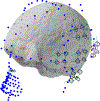
The simulated sensor array’s co-registration. The array covers the subject’s digitized scalp and their brain’s image obtained through MRI. The circles represent the OPM channel location.
Fig. 4.
Fig. 4.
Extracting phase and amplitude from the data. Both the coil driver signal and the OPM signal are fitted with a sinusoidal function. The difference between the zero crossings of the fitted functions (black arrow) portrays the phase difference.
Fig. 5.
Fig. 5.
(a) Comparison of simulation (SIM) and experiment (MEAS) reults for the case of zero remnant magnetic field (Bz0 = 0). (b) Zoomed in for 180°-out-of-phase region. ∠α = 0 indicates the magnetic signal is alinged with the x-axis.
Fig. 6.
Fig. 6.
CAPE in the OPM for a 25 Hz, sinusoidal signal with an amplitude of 0.33 nT. Simulated phase (a) and normalized amplitude (b). Measured phase (c), and normalized amplitude (d). The legend refers to the magnitude of the static magnetic field on the laser propagtion axis (Bz0); Bx = cos(α) × sin(2π × 25 × t) and By = sin(α) × sin(2π × 25 × t).
Fig. 7.
Fig. 7.
Simulated (a) and measured (b) amplitude error of the OPM caused by CAPE. The larger the Bz0 the larger the error. The error is calculated as the amplitude difference with the case of no remnant static magnetic field (Bz0 = 0). For signals in vicinity of α=90° the error can be as large as 30%. The asymmetry in the measured error is due to light shift.
Fig. 8.
Fig. 8.
Measured change in the sensitive axis orientation (°) vs. the DC magnetic field on the laser’s propagation axis (Bz0) for a 25 Hz signal. CAPE rotates the sensitive axis by a measured gain of 2.86 °/nT and a simulated gain of 3.33 °/nT. The slight difference between the two is attributed to different relaxation rates.
Fig. 9.
Fig. 9.
Measured zero crossing error in OPM array; a 25 Hz magnetic dipole is activated and its signal is captured by a 16-ch OPM system. The inset displays the zero crossing attributed to expanded phase transition region due to CAPE.
Fig. 10.
Fig. 10.
The misalignment of measured channels’ peak response at M20 SEF response. The observed misalignment could be stemmed from CAPE.
Fig. 11.
Fig. 11.
CAPE-induced phase and normalized amplitude for various signal frequencies. Bz0 = −4.8 nT except for “No CAPE” which has Bz0 = 0 and a singal frequency of 5 Hz.
Fig. 12.
Fig. 12.
Rate of change in sensitive axis rotation for various frequencies. In the presence of remnant static magnetic field, the sensitive axis is frequency dependent and higher frequencies’ sensitive axes is less impacted by CAPE.
Fig. 13.
Fig. 13.
CAPE-induced amplitude error. The error is symmetric around Bz0 = 0, increases with magnitude of remnant field and has a bandpass dependency on signal frequency.
Fig. 14.
Fig. 14.
The mean and standard deviation (bars) for source localization error; the x-axis is the standard deviation of the remnant static magnetic field on the laser propagation axis selected from a normal gaussian distribution.

References

    1. Borna A, Carter TR, Colombo AP, Jau YY, McKay J, Weisend M, Taulu S, Stephen JM, Schwindt PDD, 2020. Non-invasive functional-brain-imaging with an OPM-based magnetoencephalography system. PLoS ONE 15 (1), e0227684. - PMC - PubMed
    1. Borna A, Carter TR, Goldberg JD, Colombo AP, Jau YY, Berry C, McKay J, Stephen J, Weisend M, Schwindt PDD, 2017. A 20-channel magnetoencephalography system based on optically pumped magnetometers. Phys. Med. Biol 62 (23), 8909–8923. - PMC - PubMed
    1. Boto E, Bowtell R, Kruger P, Fromhold TM, Morris PG, Meyer SS, Barnes GR, Brookes MJ, 2016. On the potential of a new generation of magnetometers for MEG: a beamformer simulation study. PLoS ONE 11 (8). - PMC - PubMed
    1. Boto E, Holmes N, Leggett J, Roberts G, Shah V, Meyer SS, Munoz LD, Mullinger KJ, Tierney TM, Bestmann S, Barnes GR, Bowtell R, Brookes MJ, 2018. Moving magnetoencephalography towards real-world applications with a wearable system. Nature 555 (7698), 657 -+. - PMC - PubMed
    1. Cohen-Tannoudji C, Dupont-Roc J, Haroche S, Laloë FJRPA, 1970. Diverses résonances de croisement de niveaux sur des atomes pompés optiquement en champ nul. I. Théorie 5 (1), 95–101.

Publication types

LinkOut - more resources